UFS
Feature:
Supported Models:
| BF6264B | BF7264B | BF7264B+ | BF7264 Pro |
|---|---|---|---|
| ● | ● |
BF7264B+/Pro has two USB holes at the front.
It provides the protocol analyzer function of MIPI M-PHY UFS2.1 (supports UFS3.1 commands).
Specifications:
- BF7264B+/Pro, 32Gb RAM, MIPI M-PHY UFS2.1 Probes

- Fully supports MIPI M-PHY UFS2.1, and support UFS3.1 commands.
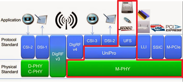
- MIPI M-PHY 3.0, Up to 5.8Gbps ( Gear 3, Rate A / B ), 2 Lanes
- MIPI Unipro 1.8
- JEDEC UFS 2.1
- JEDEC UFS 3.1 commands
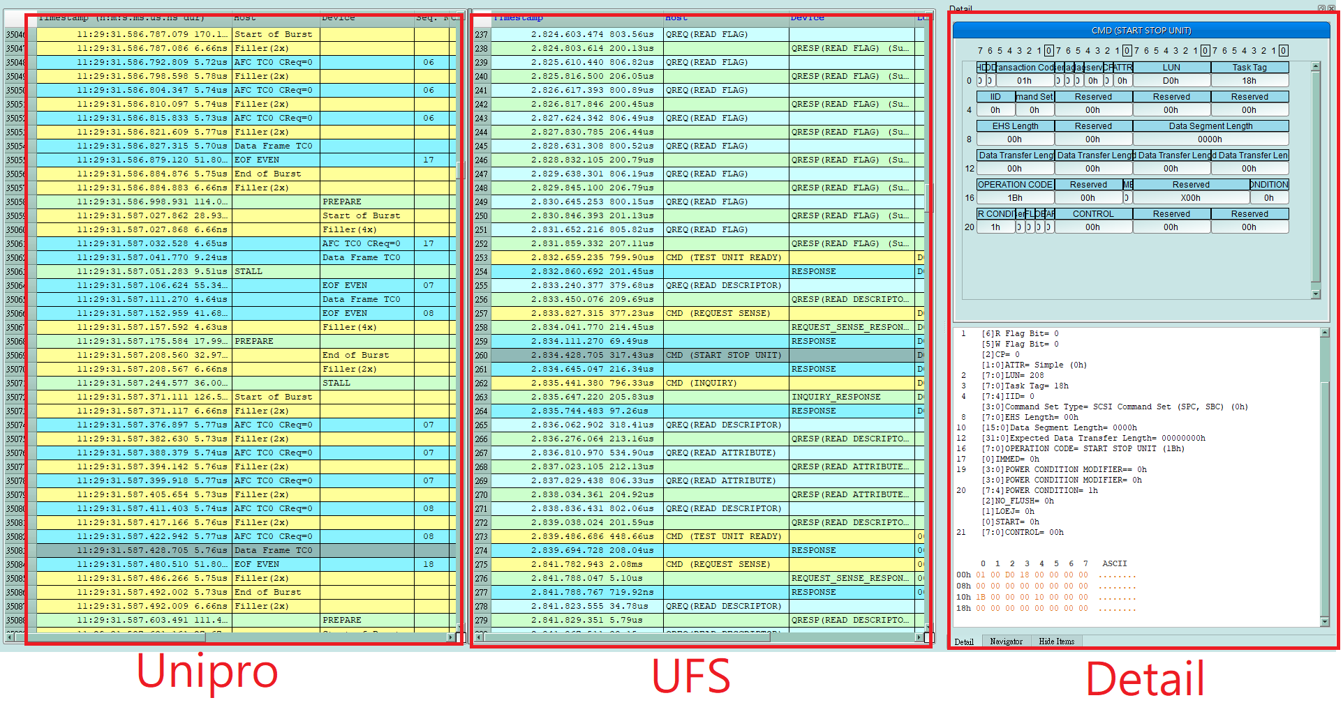
- Can simultaneously display Unipro or UFS protocol packet data in tabular form, including command parsing
- Use 32Gb RAM as the buffer to stream all M-PHY data into the SSD HD in order to record all data flow from PWM Mode to High Speed Mode.
- “Data Filter” filters unwanted data to save memory.
- “Search” searches specific data.
- “CRC Packet” displays and counts CRC
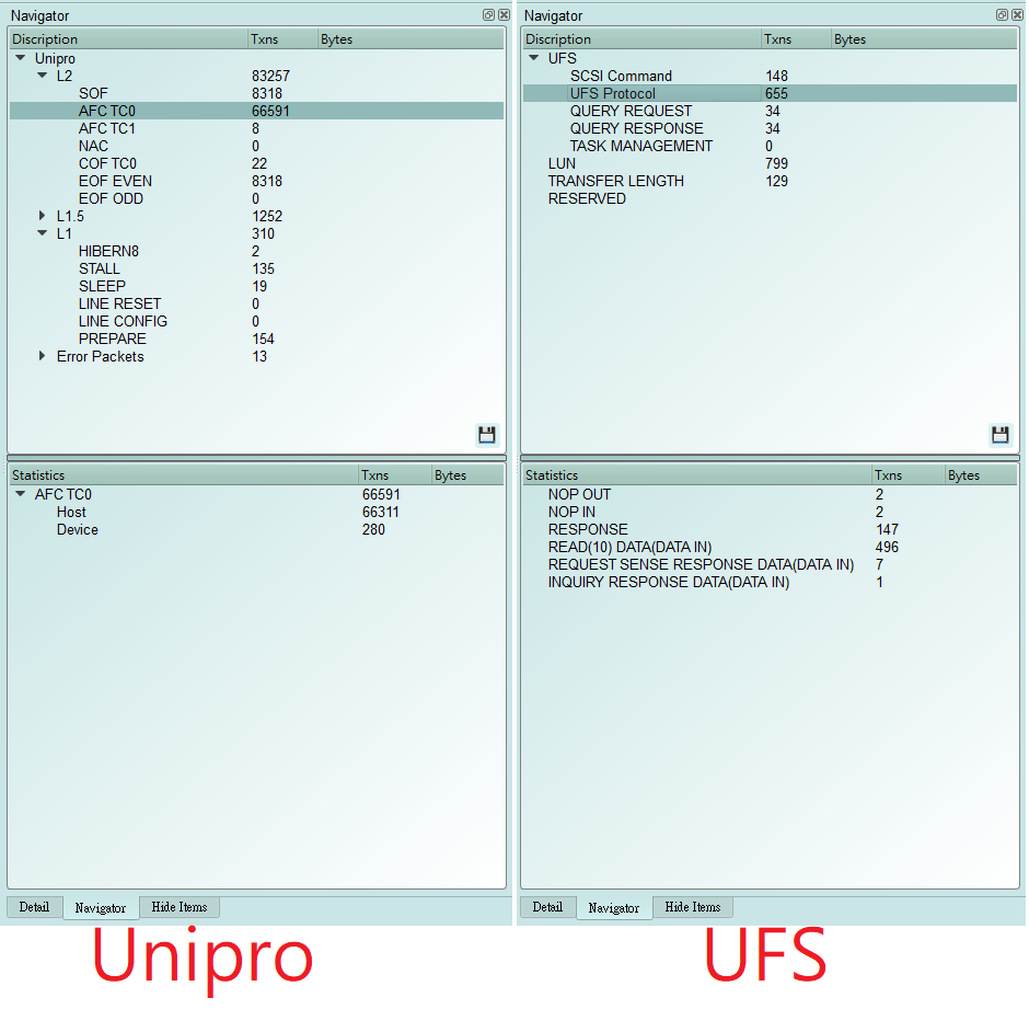
- Unipro / UFS command statistics include numbers of packets, individual command, different data length, and errors
- Command trigger
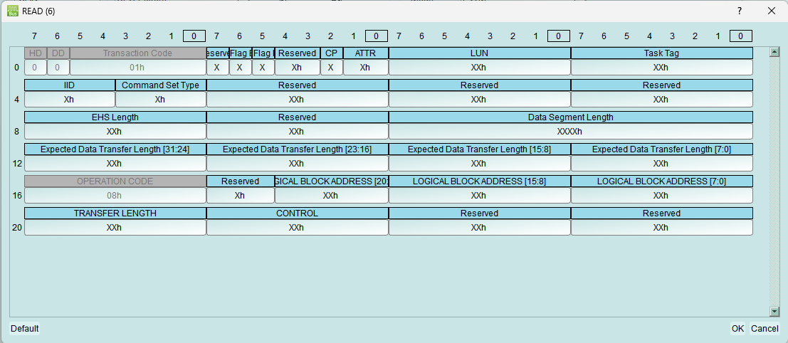
- Trigger parameters include commands and data in order to cover all kinds of packets.
- CRC Error, Unknown packet
- VCC drop, VCCQ2 drop
- The Trigger-Out port is to trigger a DSO to capture waveforms
9. Advanced usage of the report area
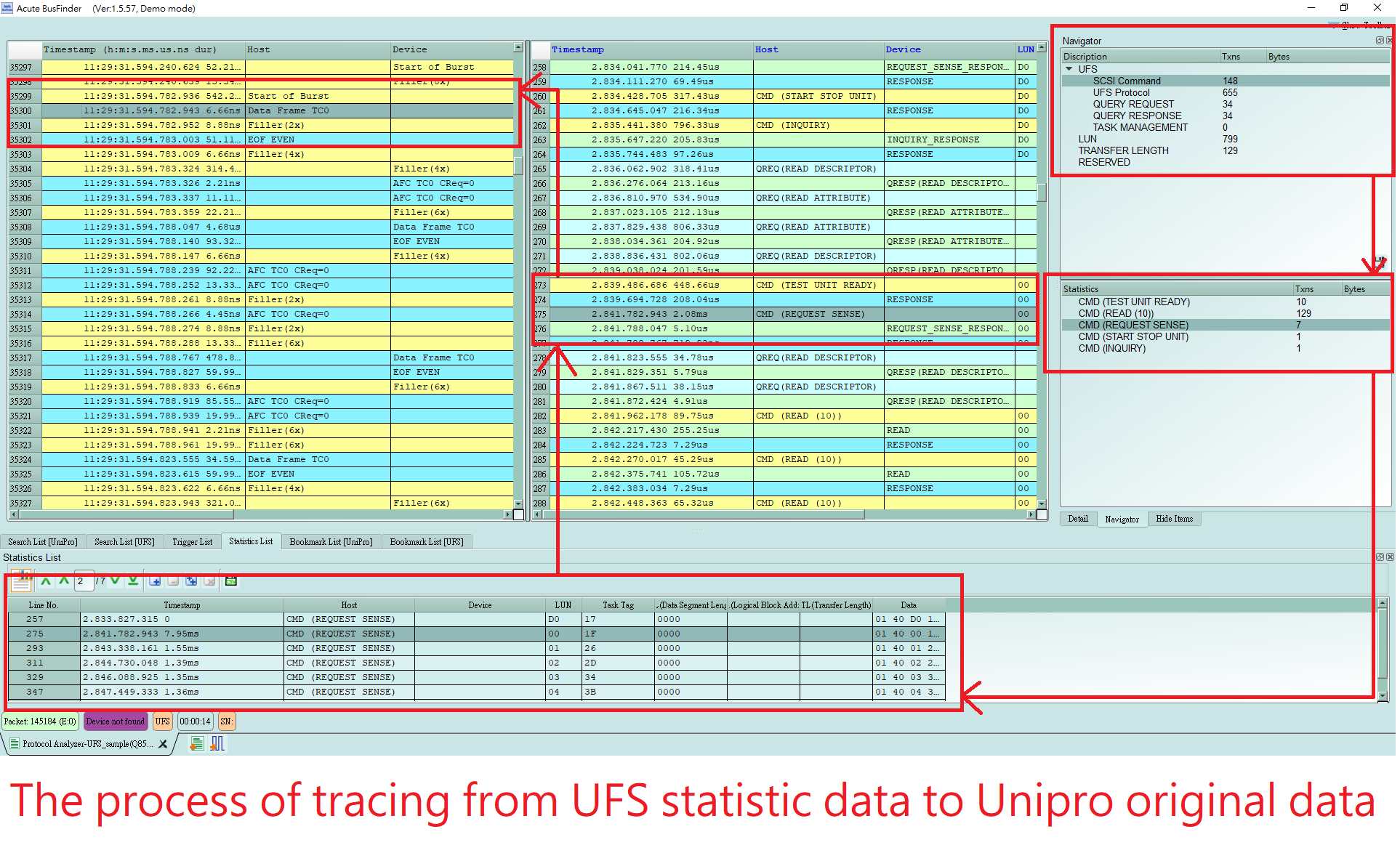
- Dual report correlation: Unipro and UFS reports are related to each other. Double-click to track the corresponding data in another report area.
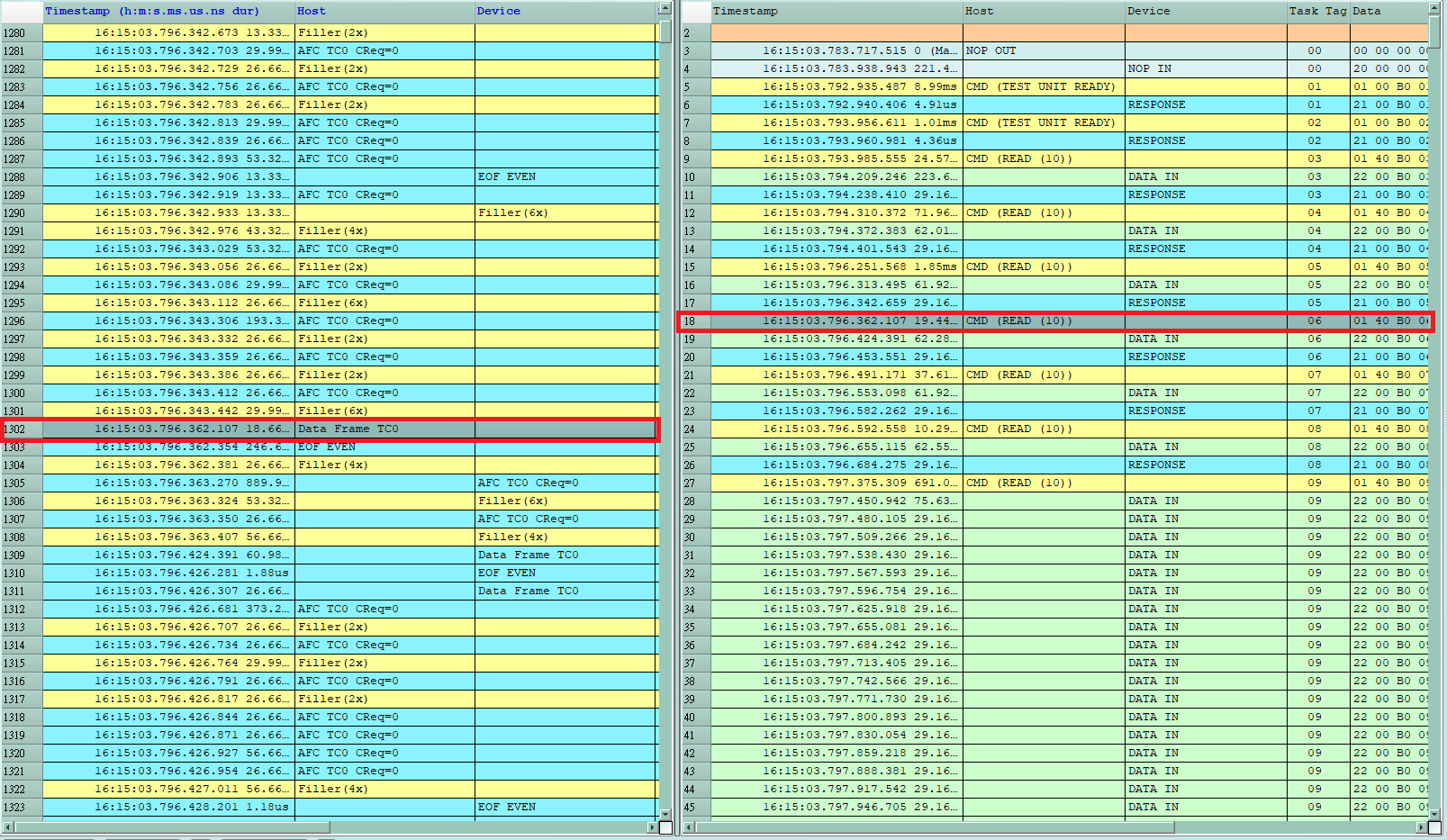
ex: Click the Unipro area report to link to the UFS corresponding report.
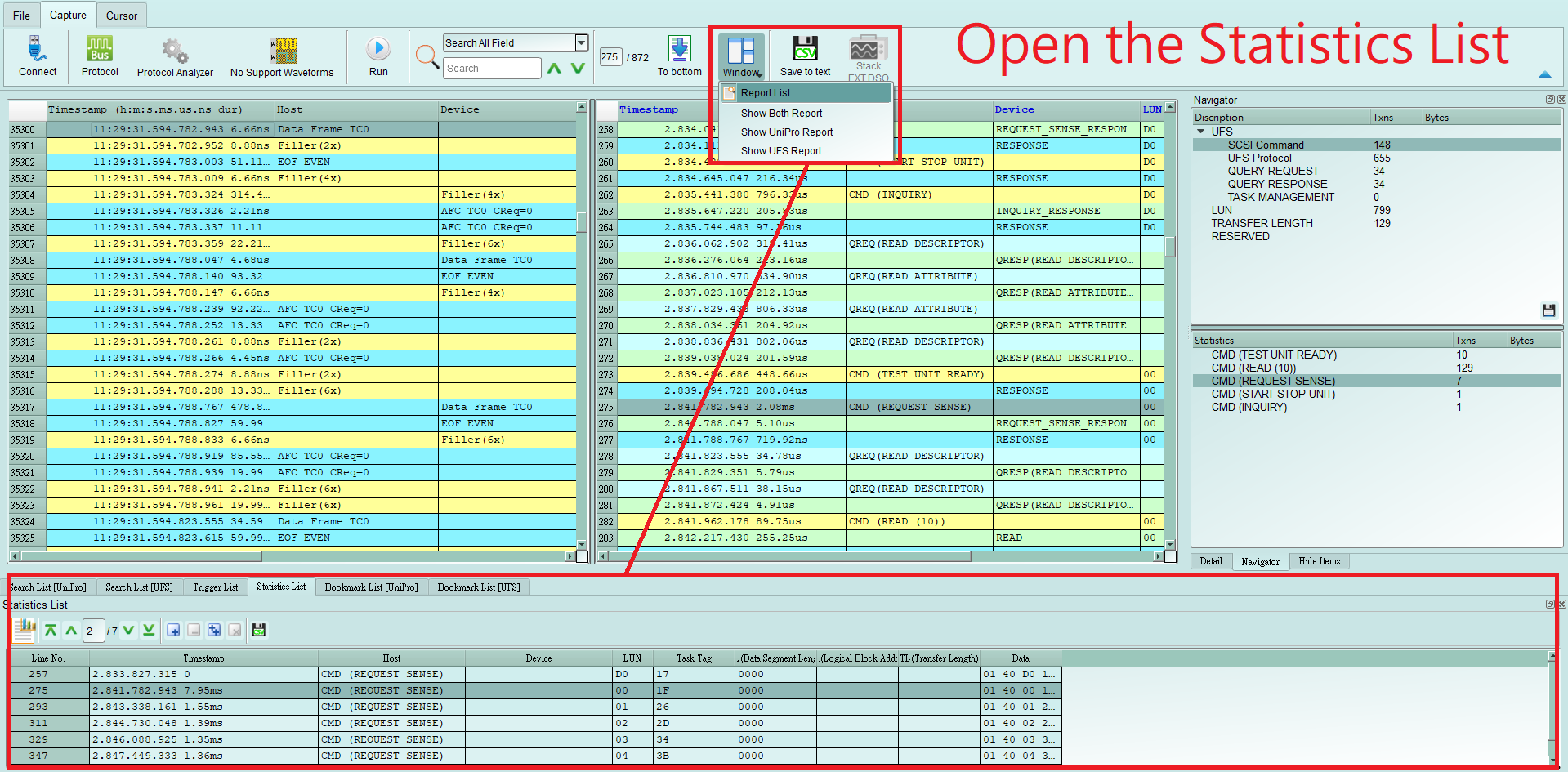
- Statistics list: Quickly categorize and track the location of data with statistical functions.
- UFS Settings
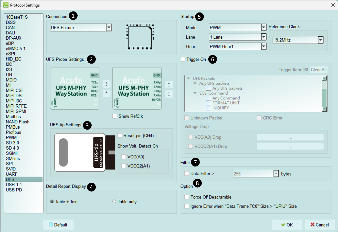
- Connection: You need to select the connection method between BF7264B+/Pro and the test object
- UFS Probe Settings: Exchange the p/n of the same Lane. The RefClk Option lets you observe whether RefClk is operating.
- UFS-tip Settings:
- To enable the UFS Reset pin option, connect the reset pin to the UFS-tip CH4 position of the UFS Probe. When the protocol analysis receives the Reset signal, it resets the power mode and returns to PWM mode.
- When Show Volt. Detect Ch is turned on, the detected voltage value is displayed whenever the voltage changes.
- Detail Report Display: Add the detail report as a text description.
- Startup: Set the DUT mode at the moment of capture, and set the reference clock (19.2 / 26 / 38.4 / 52 MHz). (It does not matter if RefClk is not connected, but its frequency must still be set.)
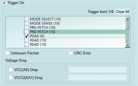
- Trigger On: You can set Unipro / UFS packet triggers (8 groups total), plus Unknown Packet and CRC Error trigger options. Two more sets of voltage detection are also available.
- Filter: When enabled, it filters out packet data beyond the set length.
- **Option: **
- Force Off Descramble: When checked, shows the scrambled data only.
- Ignore Error when "Data Frame TC0" size > "UPIU" size: When checked, ignores the error where the "Data Frame TC0" size is greater than the "UPIU" size.
FAQ
What UFS version is supported, any limitation for differential ports?
- A:
- Will the signal quality be affected during measurement?
- A: The measurement of the external instrument will inevitably have some load effect. We use the SMPM Coaxial Cable connection to reduce the interference of the object to be measured and improve the signal quality.
- Is Tx supported?
- A: No
- Precautions during measurement a. Wiring problem:
Please make sure to connection according to the “Probe and test object connection” on page 10. If the PWM is normal during measurement, but you cannot see any HS data or you can only go to 1 Lane and not 2 Lane, you should first check whether the wiring is wrong.
b. Reference clock setting method:
There are four options for Ref CLK 19.2MHz (default) / 26MHz / 38.4MHz / 52MHz in Settings. If it is not clear what the Ref CLK is used, refer to the following method. If the PWM is normal but the HS Data is wrong, please try to adjust the Ref CLK to others and try again.
- Can I specify a Unipro, UFS packet as the trigger point function?
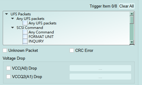
A: You can specify specific Unipro, UFS packet or Error to trigger.
- Is it possible to set a Unipro, UFS starting point, and specify how much time to capture Data?
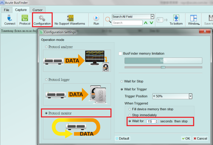
A: You can set the starting condition to the trigger item and adjust to the data monitor mode in the working mode menu. And specify the length of acquisition time.
BusFinder and Probe connection
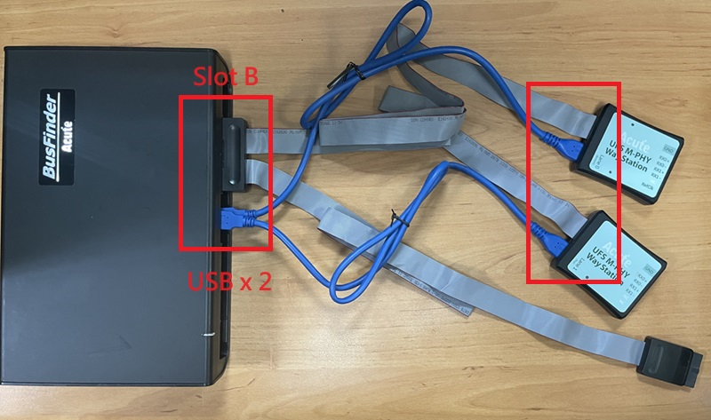
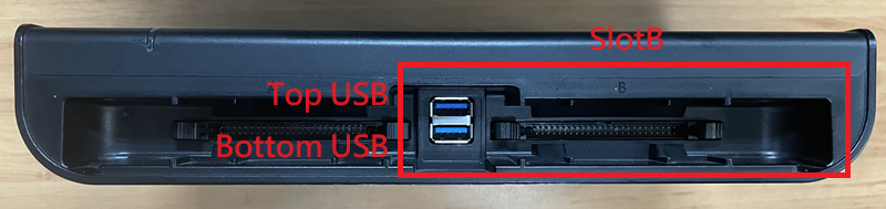
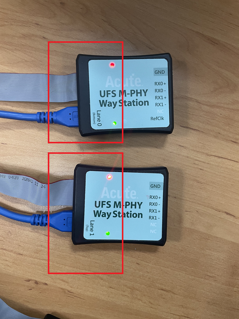
The BusFinder can only use the Slot-B to connect the UFS probe. Please note that the two USB slots on the front of the BusFinder also need to be connected to the Way Station. The upper USB slot corresponds to the Top Way Station, and the lower USB slot corresponds to the Bottom Way Station. Then start the software, choose UFS, and check whether both Way Station lights show red and green.
Probe and test object connection
a. Connect using UFS Fixture (connector)
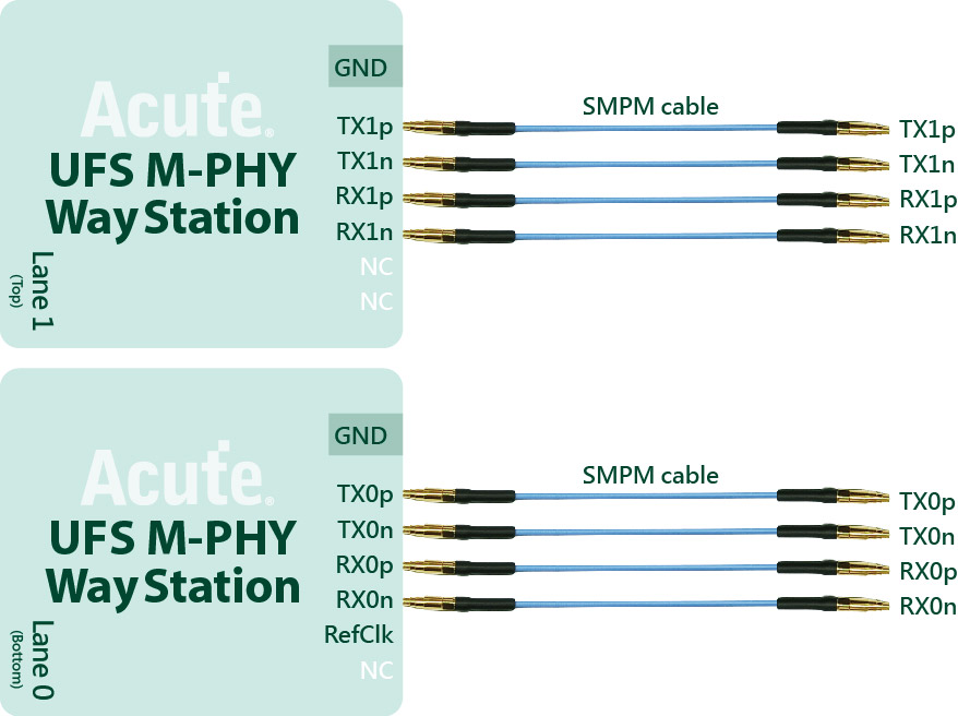
If the Host has multiple sets of connectors, it is convenient to replace the Host and UFS Chip, and directly use the SMPM Cable to connect to the Way Station without jumpers.
Since the connector uses a flexible cable to extend the signal, it is only suitable for applications where the peripheral components of the UFS Chip do not interfere.
| Components | |
|---|---|
| 1. Con Fixture | |
| 2. Con Dummy Board | 0.3mm tin balls need to be planted on the back |
| 3. Connector DF17-30DS-0.5V (HiRose Connector) |
Step1: Remove the UFS chip on your DUT, and then rebuild the solder ball on UFS chip.
Step2: Welding the connector to the position where the UFS Chip has been removed.
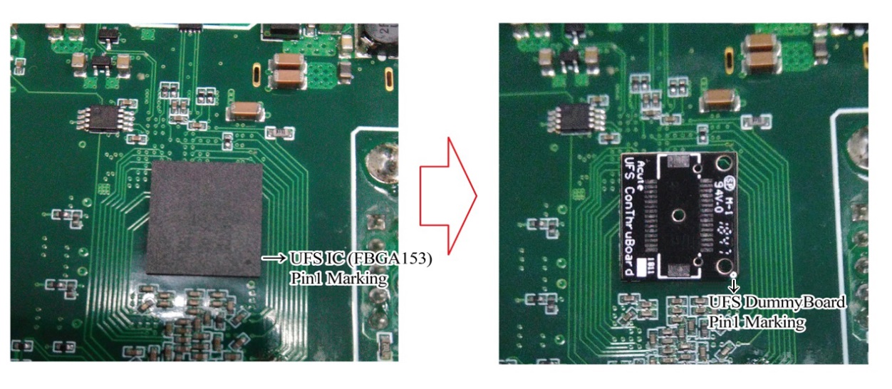
(Pay attention to the direction of Pin1 when welding the connector.)
Step3: Place the connector (DF17-30DS-0.5V) on the small board of the connector. Before welding, please pay attention to the mistake proofing between the connector and the board.
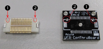
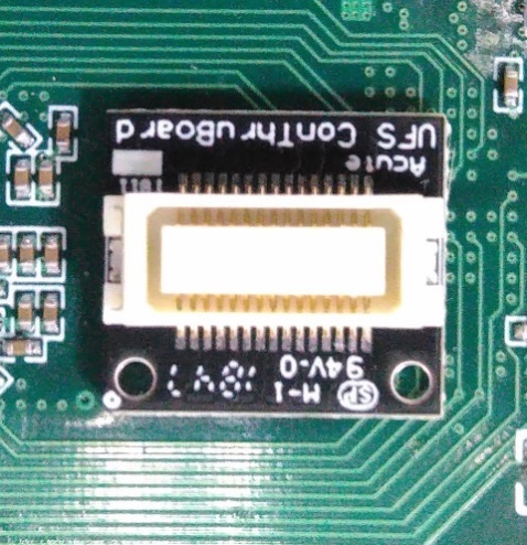
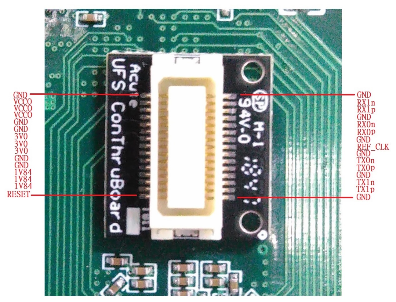
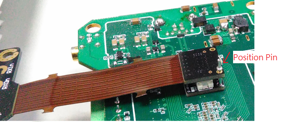
Step4: After welding is complete, check for short circuits between the pins. The pin definitions are shown below:
Step5: Connect the Con Fixture, please pay attention to the mistake proofing between the board and the Fixture.
Step6: Put the unplugged UFS Chip into the Con Fixture UFS Socket (FBGA153 Socket), and finish.
b. Use Interposer with End-tip connection
If the components around the original UFS Chip interfere, UFS Fixture cannot be used and there is no test point around the UFS Chip can jumper on, you need to remove the UFS Chip and reball the interposer on the board, and then reball the UFS chip again.
Connect the End-tip from the test point, then use the SMPM cable to connect to the Way Station.
If test points are left on the board under test, they can be used directly.
| Components | Components | Components | Components |
|---|---|---|---|
| Interposer | |||
| End-tip (FPC) | End-tip Connector (FPC) | ||
| Combined |
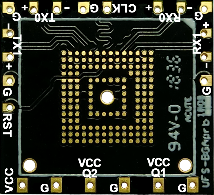
(Interposer Pin Define)
C. Connect using End-tip
If the board has a test point that can be jumpered, it can be used directly. After the End-tip is connected to the test, there is no need to use a booster board.
The UFS standard terminal soft board resistance is 250ohm, which can be used directly under normal circumstances.
If you want to shorten the jumper distance to improve signal quality, you can use the following resistance bridge method.
To use the resistance bridging method without jumpers (as shown in the figure below), the End-tip needs to be modified.
Modification process:
Step1: Remove the resistor, cut off the head, and reserve 2 welding point.
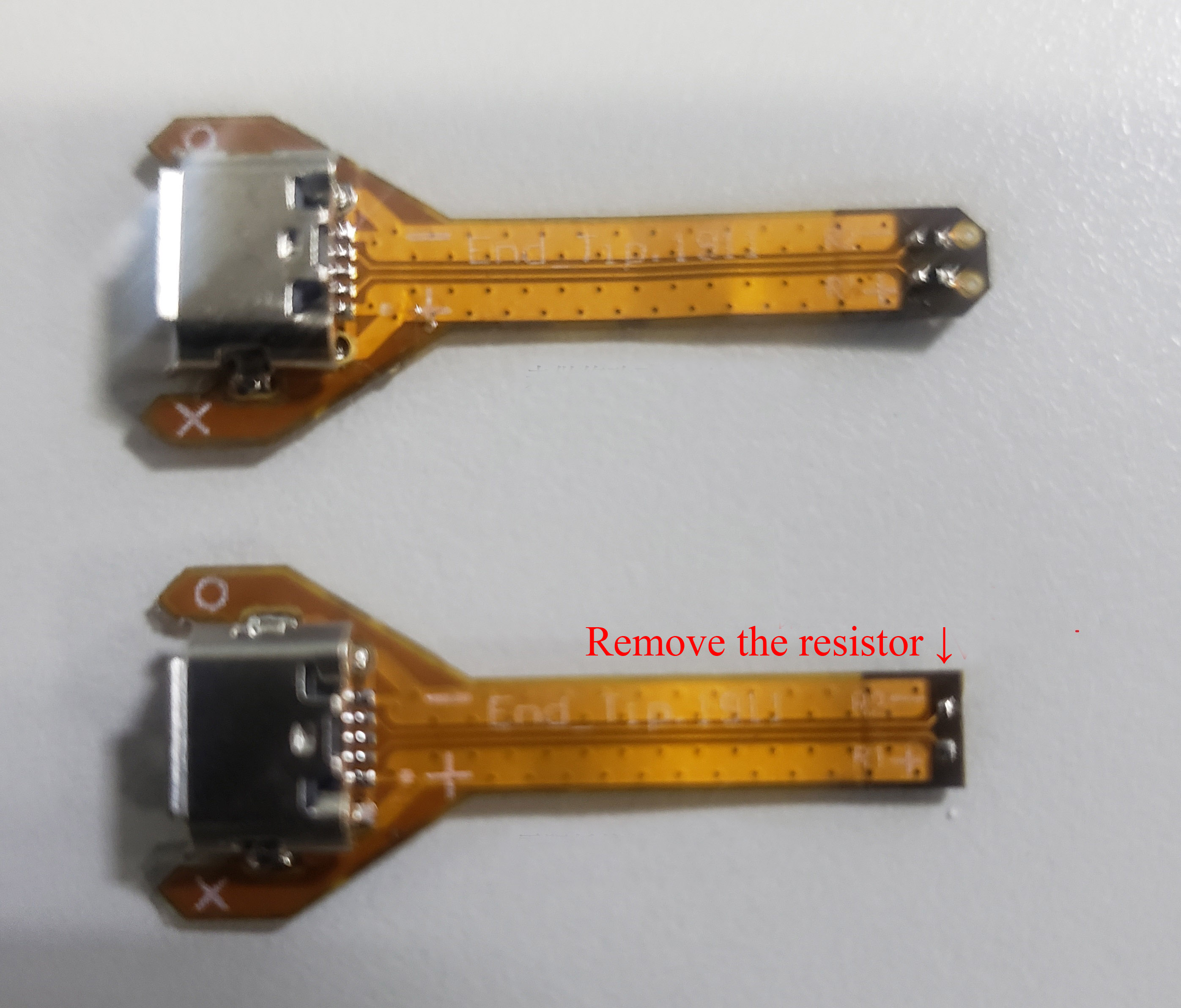
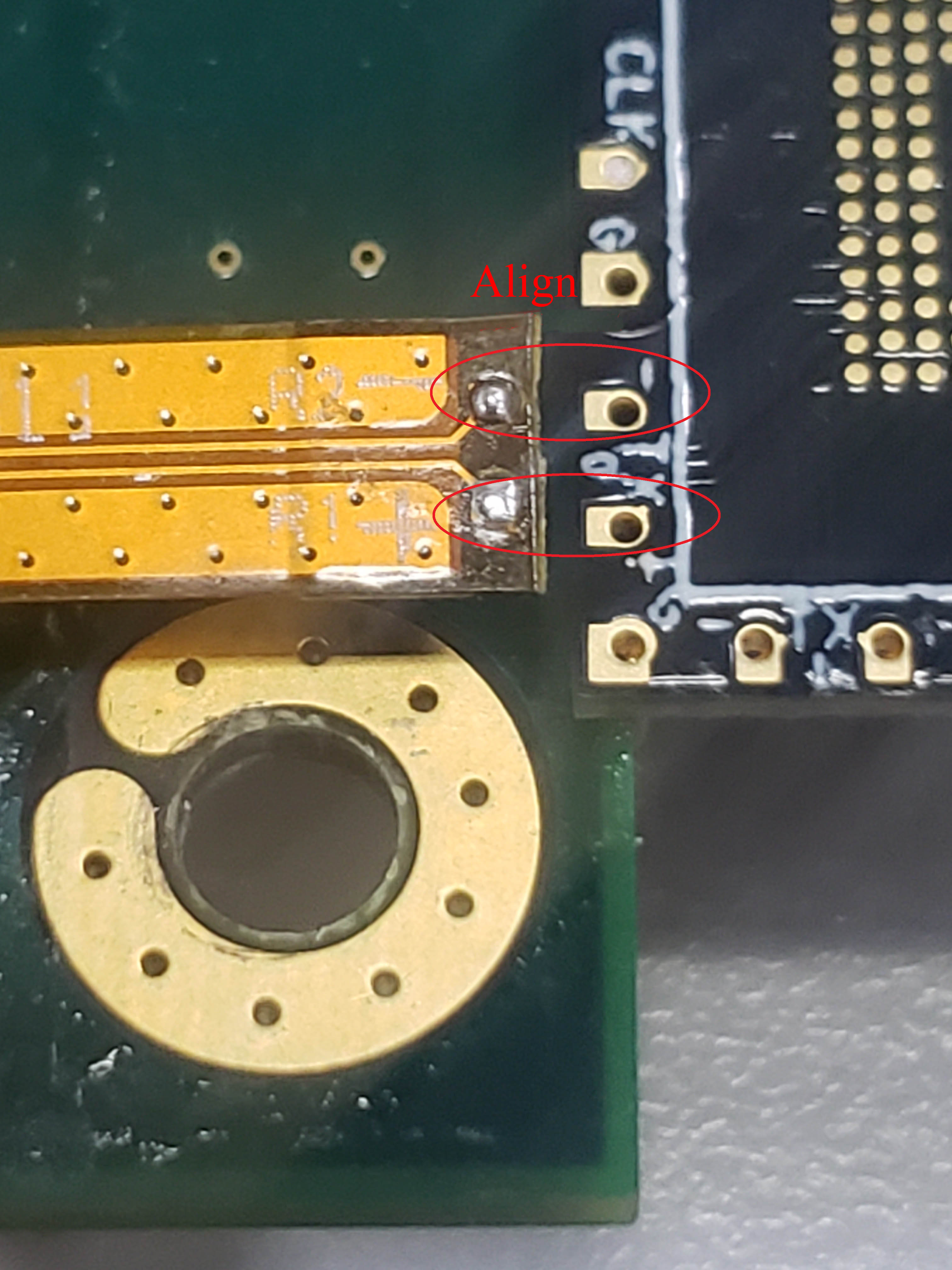
Step2: After the modification, aligning the P / N welding point between the End-tip and the interposer. Welding the resistor 250ohm (4 groups of data + 1 CLK), and the Gnds.
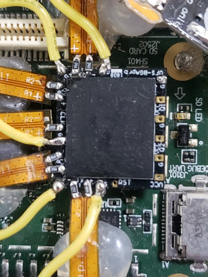
In this way, the shortest distance makes the signal quality better than the End-tip jumper connection.
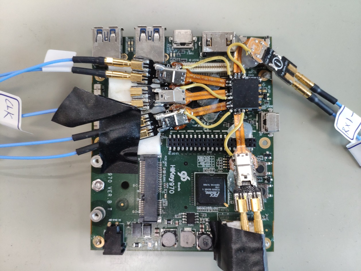
Way Station connection
- Please install UFS Probe in Slot B of BusFinder 7264B+/Pro
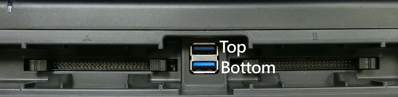
Each Way Station has a USB type B interface, please use the corresponding USB cable to install it to the BusFinder front panel. When installing, please check the installation according to the top/bottom of the Way Station nameplate mark.