eDP
Feature:
Supported Models:
| BF6264B | BF7264B | BF7264B+ | BF7264 Pro |
|---|---|---|---|
| ● | ● | ● |
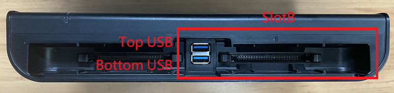
BF7264B/B+/Pro has two USB holes at the front.
The host keeps all the functions of its predecessor, the BF6264B, and adds the eDP 1.4a analyzer function.
eDP1.4a solution, the specifications are as follows:
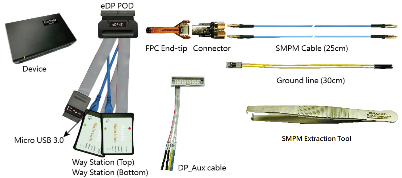
- BF7264B/B+/Pro, 32Gb RAM, with eDP1.4a probe set
-
Support eDP V1.4a(Fast Training Pattern is not supported) Up to 5.4Gbps per lane, 4 Lanes
-
Can display eDP1.4a protocol packet data in table format, including DP Aux Channel command analysis
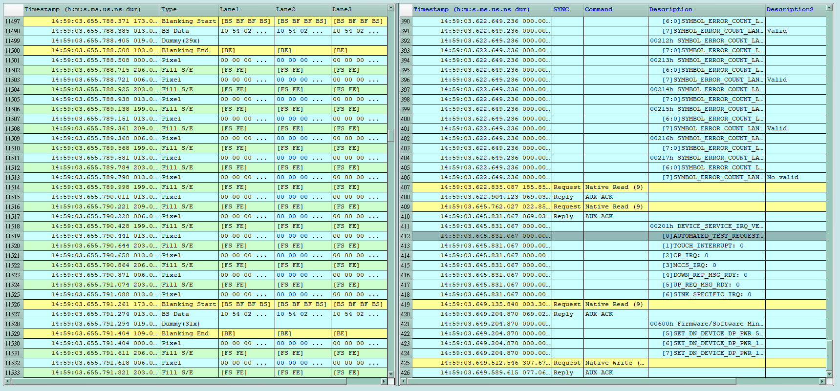
- Use the 32Gb RAM memory of the protocol analyzer and the computer hard disk to store eDP communication data through USB3.0 interface streaming transmission to ensure that the data during the collection process is intact and not lost.
- Provides Filter function, you can choose to filter out unnecessary Dummy, image data, and Filling S/E to save memory and increase the acquisition time.
- Provide search information function
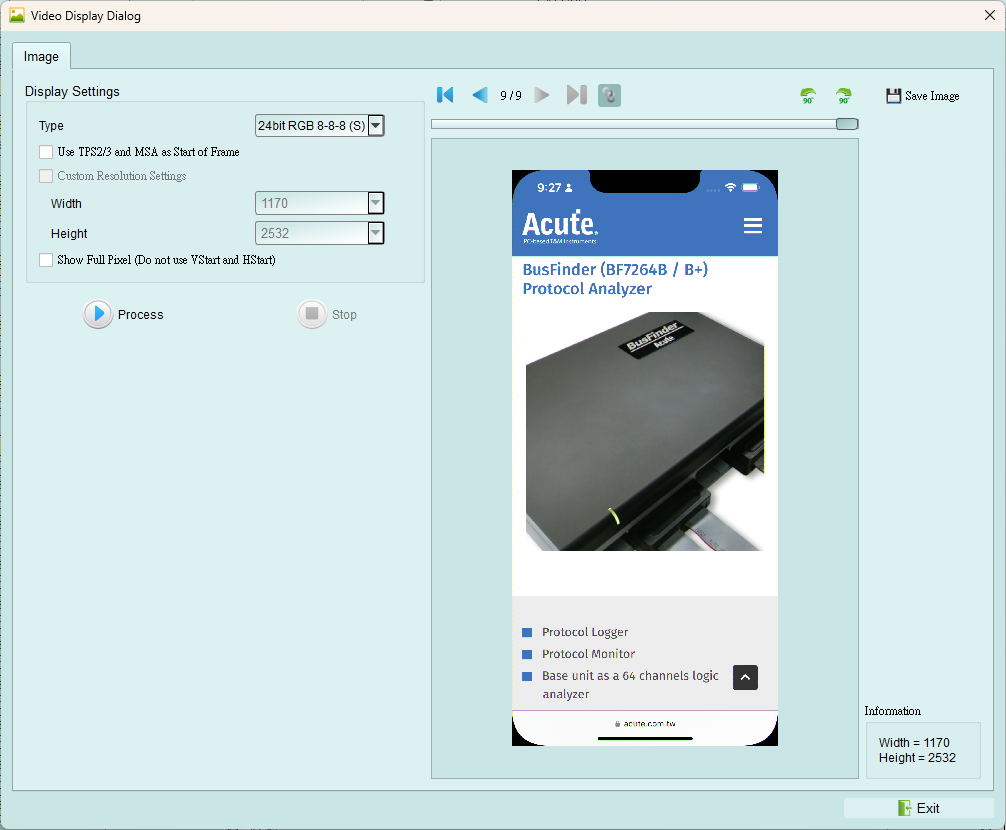
Can display eDP image data, including RGB, YCbCr formats, and compressed DSC type packets. Please refer to Appendix 1 for details.
- eDP command statistics function, including total number of packets, number of individual commands, error number statistics, and Lane Skew statistics
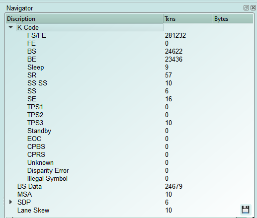

eDP Lane Skew display and statistical explanation
MainLink's main report area will display the order of each Lane data acquisition behind TPS2-TPS4. The earlier the data is retrieved, the greater the value will be. Taking the above picture as an example, Lane 0 is intercepted first (the value is +3), Lane 1 is intercepted second (the value is +1), and Lane 2 is intercepted last (the value is +0).
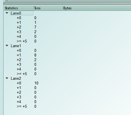
(Unit: Taking MainLink 5.4Gbps as an example, 1/ 5.4Gbps * 20 ≒ 3.7ns)
(Error: about 2 Bytes)
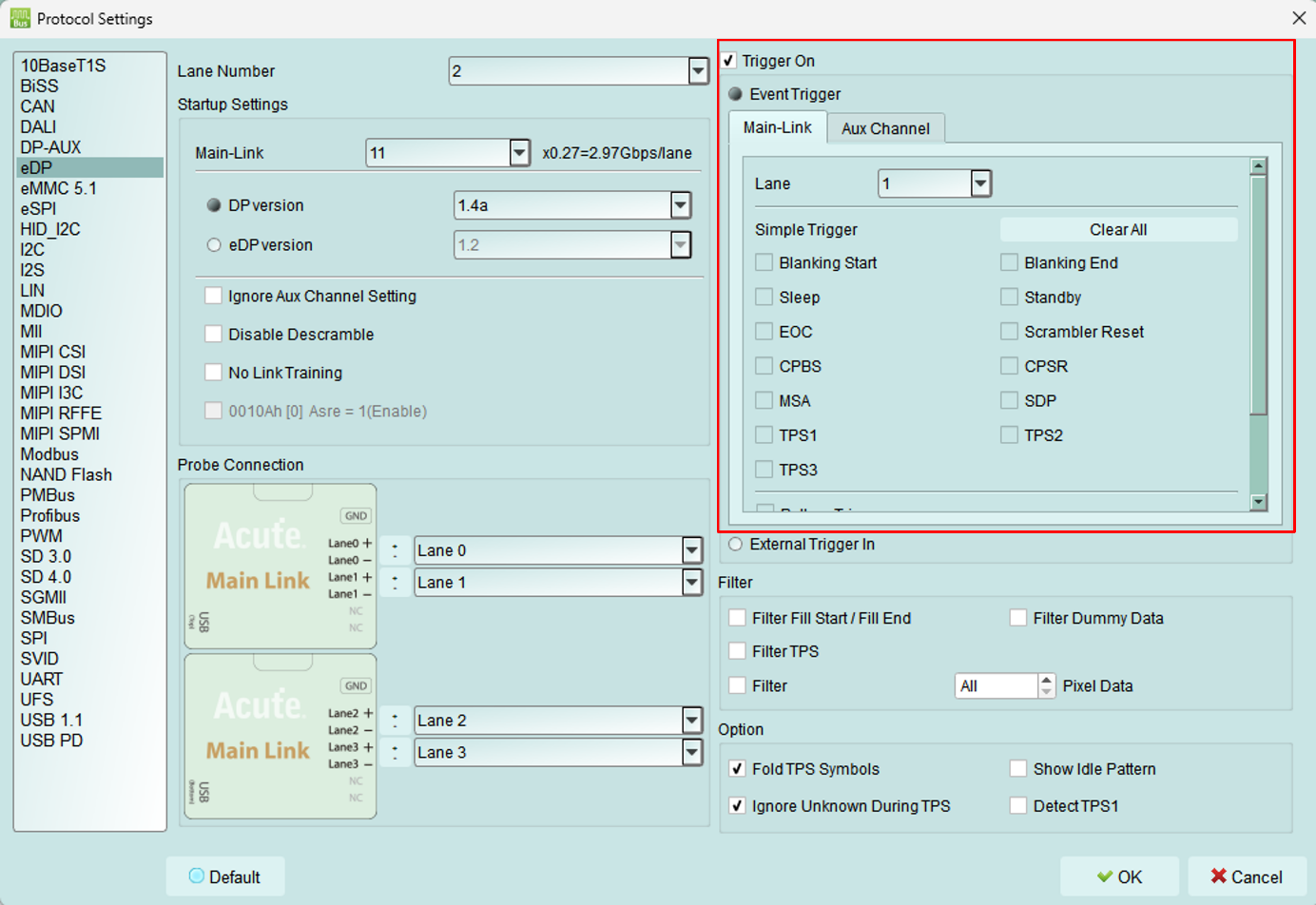
- eDP Trigger On
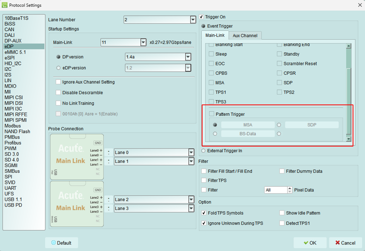
- Trigger parameters include command and parameter data. MSA, SDP, BS-Data, and Aux data can be input as trigger conditions.
- Can trigger eDP K Code combination, ex: Blanking Start[BS], Scrambler Reset[SR BF BF SR].
- An external oscilloscope can be triggered simultaneously through the Trigger-Out jack.
- Other setting instructions
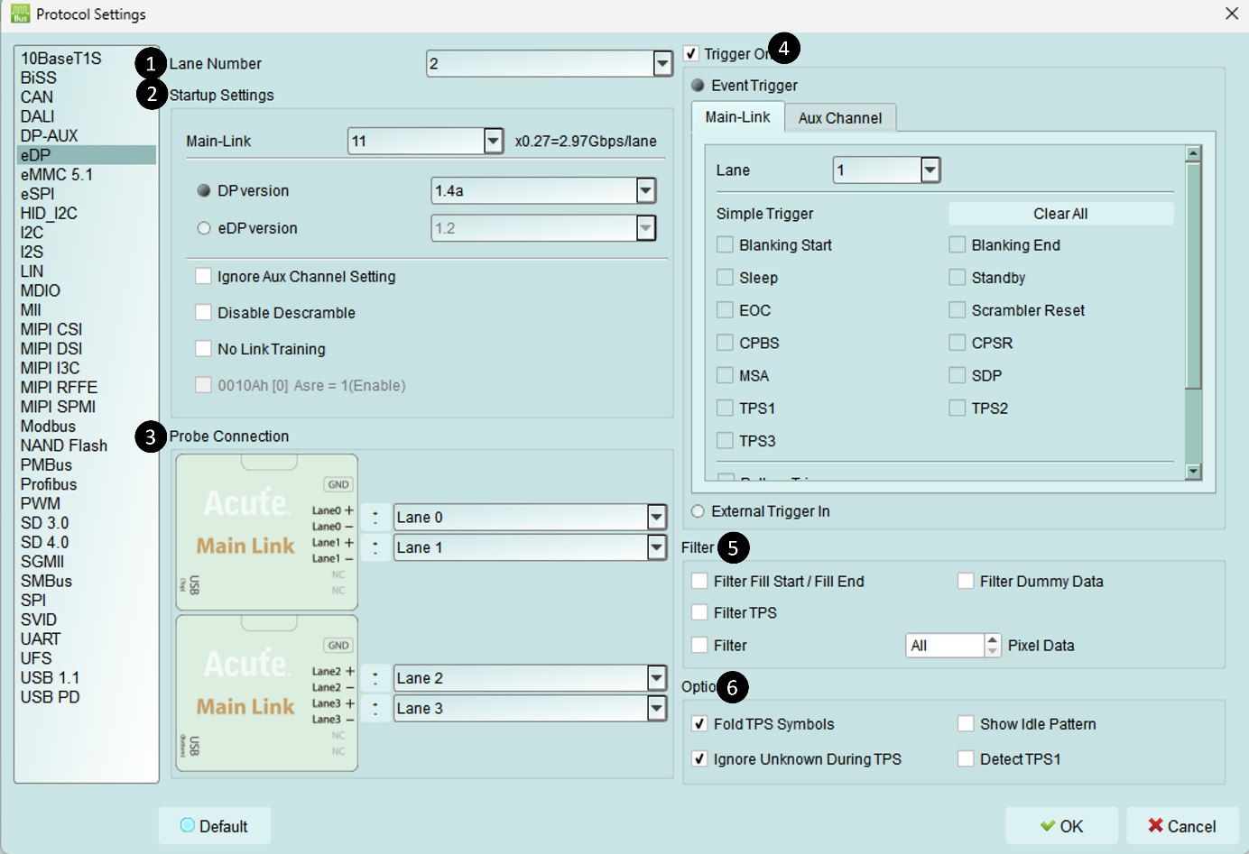
(1). Lane Number: The number of wires used by the object under test must be set
- (2). Startup Settings: When starting measurement, the various status settings of the object under test are set. If it is grabbing, AUX
- If there is no parameter setting, you must set
- Main-Link Rate: Need to set the speed of DUT under test.
- DP version/eDP version: Select the version analyzed by the Aux Channel of the object under test.
- Ignore Aux Channel Settings: If checked, parameter settings from AUX will be ignored
- Disable Descramble: If checked, descrambling is not performed.
- No Link Training: If the device under test does not send TPS when waking up, it must be checked.
- 0010Ah [0] Asre = 1(Enable): Can be set when eDP is selected in the above version. If checked, 0010Ah bit 0 will be set to 1, Enable Alternate Scrambler Seed Reset. (3). Probe Connection: Channel setting, exchangeable channel number and P/N
(4). Trigger On: After the trigger is successful, the data will be marked in the main Report area and removed from BusFinder. The square Trigger Out signal hole sends out TTL 5V Pulse, which can be connected to an oscilloscope to view the real waveform.
- The upper part is divided into MainLink and Aux Channel
- MainLink must set the Lane to be triggered and the K Code to be triggered.
- Aux Channel is the command of Source and Sink.
-
The lower part is Pattern Trigger, which can set the pattern of MSA/SDP/BS-Data/Aux Channel. (5). Filter: After checking, the instrument will filter the corresponding commands or image data, which can greatly reduce the amount of data.
-
Filter Fill Start / Fill End: Filter Fill Start and Fill End
- Filter Dummy: Filter Dummy
- Filter TPS: Filter TPS 1-4
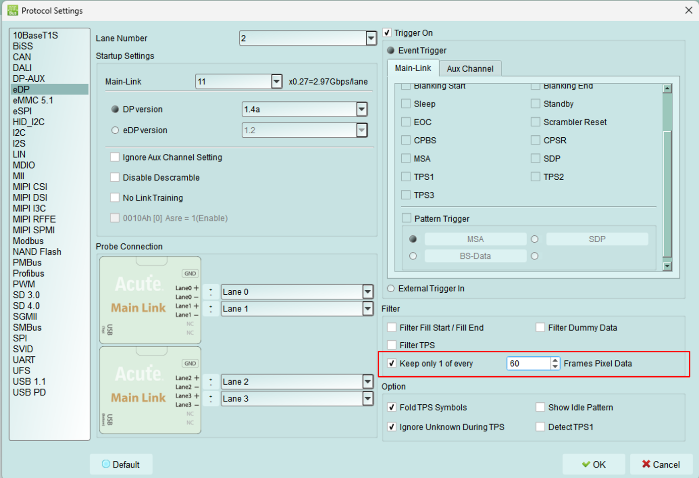
- Filter Pixel Data: All images or part of the images can be filtered (after selecting the number x, one image will be captured for every x image data), with a maximum limit of 128. (6). Option: Other settings
a. Fold TPS Symbols: If checked, a series of TPS will be folded in the main Report area and the number will be displayed at the back of the report.
b. Ignore Unknown During TPS: If checked, the Unknown command will be ignored between Sleep-TPS-Scrambler Reset (because the instrument has not aligned the Lane data during this interval, an error will occur)
c. Detect TPS1: If checked, enable the detection of TPS1 function (TPS1 cannot be fully aligned with D Code)
FAQ
- Which version of eDP specifications are supported? Are there any limitations on the number of Differential pairs or ports?
- A: Supports eDP 1.4a, up to 5.4Gbps, 4 Lanes
- Will the signal quality be affected during measurement?
- A: Connecting an instrument always adds some load effect. We use the end-tip connection method with an SMPM coaxial cable to reduce interference from the object under test and improve signal quality.
-
Does it support signal transmission (Tx)? A: No, it does not support sending signals.
-
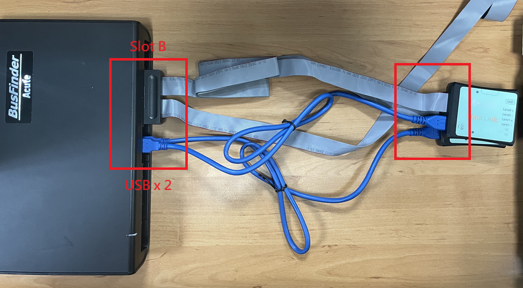
How to connect the host and probe?
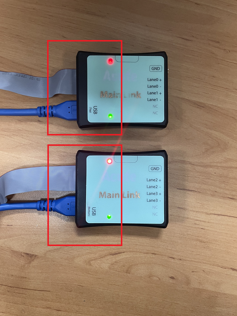
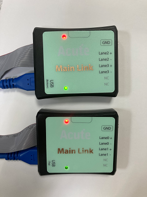
- A: The host can only use Slot B as the probe connection slot. Please note that the two USB slots on the front of the host also need to be connected to the Way Station. The upper USB slot corresponds to the Top Way Station and the lower USB slot corresponds to the Bottom Way Station. Do not connect them incorrectly, otherwise will not be measurable. After connecting, please pay attention to whether the two Way Station lights have a red light and a green light.
- How to connect the probe to the object under test?
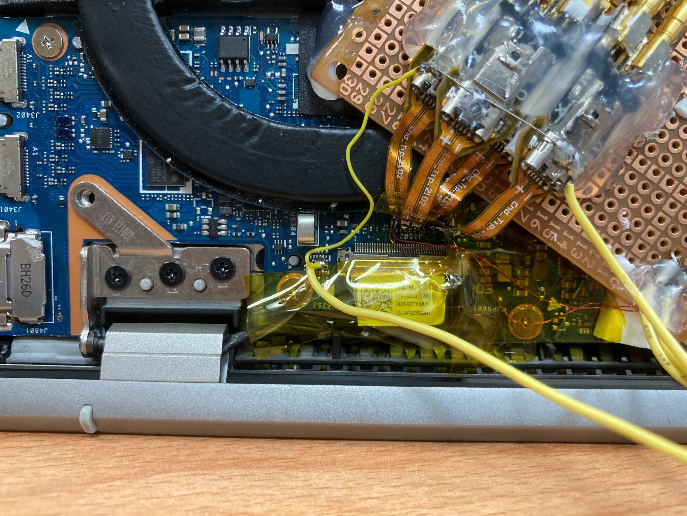
- A: Soldering wire: Use end-tip to connect the object under test in the form of a jumper. At this time, the length of the jumper must be less than 5mm to improve signal quality. (Refer to Appendix 2)
- If the jumper cannot be shortened to within 5mm, solder a 100Ω resistor to the signal end under test, then run the jumper from the resistor to the end-tip. This lets the jumper be about 3cm long.
- Step 1: First connect the SMPM-SMPM cable to the End-tip and confirm that you hear the positioning click.

- Step 2: Solder the jumper last, so that plugging in the SMPM cable after soldering does not disturb it.
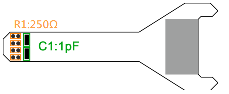
- ※ The end-tip's R1 resistor is 250Ω and its C1 capacitor is 1pF. If the wire is damaged during soldering, you can replace it yourself.
- How is the DUT grounded?
- A: Since the device and the system under test still need to share the same ground, you can first connect the GND Port on the Way Station to the GND of the object under test. Both Way Stations must be connected.
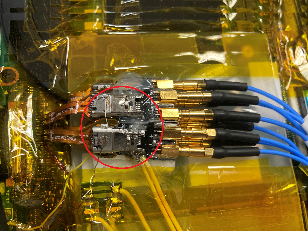
Unless the signal quality is too poor or the interference is too large, and many errors occur after analysis, the best effect can be achieved by connecting each End-tip to ground, as shown in the red circle in the figure below.
- The Main-Link of the object under test cannot receive the signal.
- A: Confirm that the probe is connected correctly and check whether the red and green indicators on both Way Stations light up at the same time. Lighting up at the same time is normal.
- In addition, please confirm whether the steps in FAQ4 and FAQ5 are correct, refer to Appendix 3, use the waveform viewing function, and make sure the wiring is correct before starting measurement.
- Is there a function to specify a Type or Aux command as a trigger point?
- A: Specific Type/Aux commands can be specified for triggering.
- Is it possible to set a starting point (such as Aux CMD) and specify how long to capture the data?
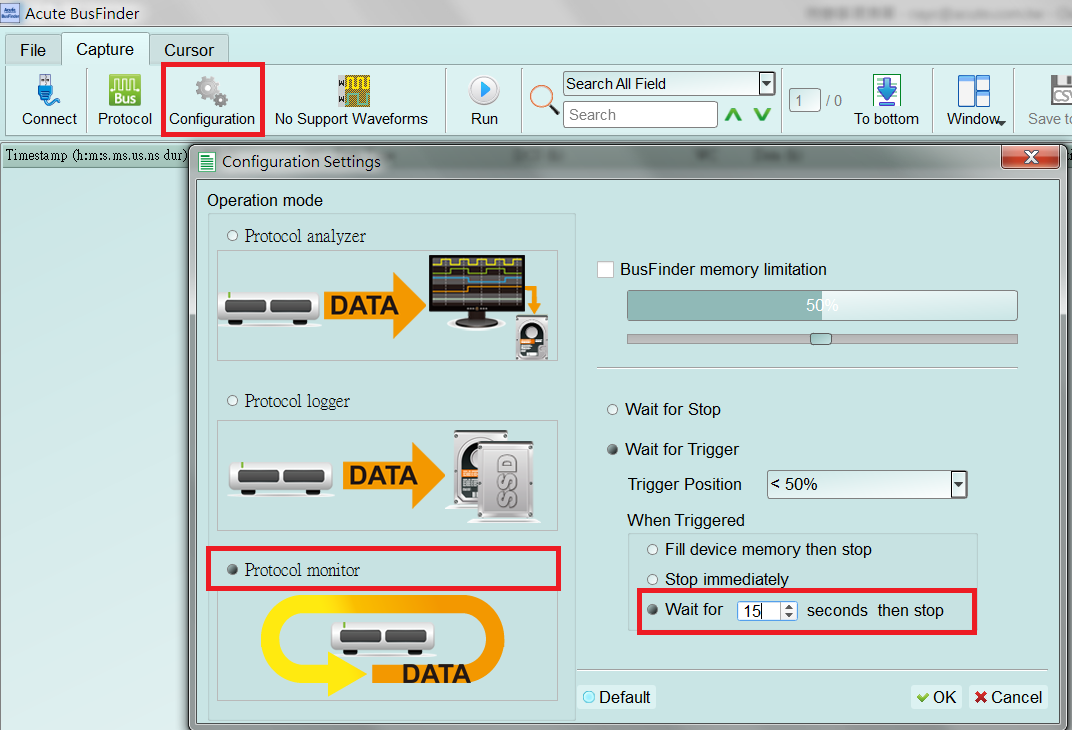
A: You can set the starting condition after triggering the project and adjust it to the data monitor mode in the work mode menu. And specify the capture time length.
- The probe and the object under test have been connected according to the above method, but the signal cannot be acquired correctly?
- A: When eDP captures signals, it must be captured from the boot up. If it is captured from the middle, some information will be missing.
- If you cannot capture the screen after startup due to excessive video signals, you can adjust the Filter settings to reduce the amount of pixel data. After all, if a screen is updated 60 times per second, the difference from updating once is not much different in terms of screen viewing.
- The setting method is as follows in the red box below
- The Aux Channel measurement data is abnormal or cannot be measured?
- A: You can use the LA function to observe whether the Aux Channel signal is received normally.
- The following is the method to enable LA measurement AUX Channel:
- Click on the bottom left to add a new protocol analysis channel and select DP_AUX
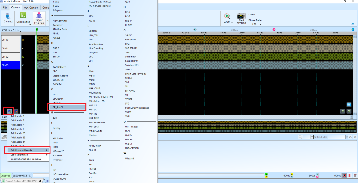
- Change the channel setting to B8 and turn on Show DPCD
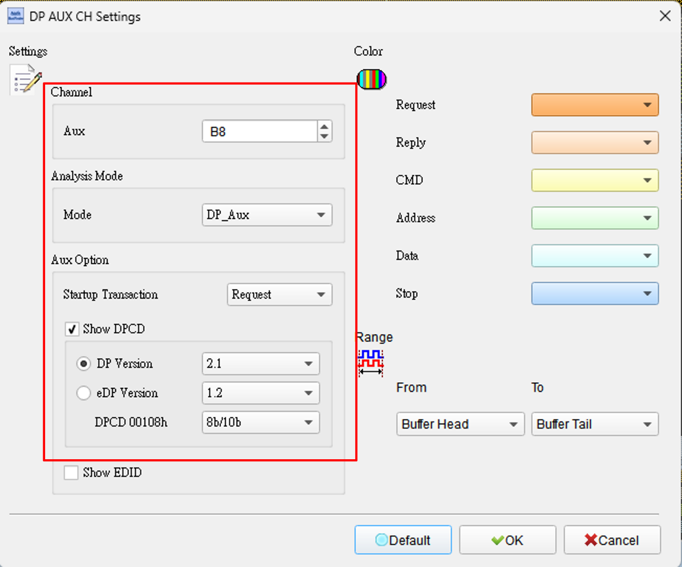
- Change the Sample Rate to 20MHz and change the channel to A0-B31 to start capturing DP_AUX
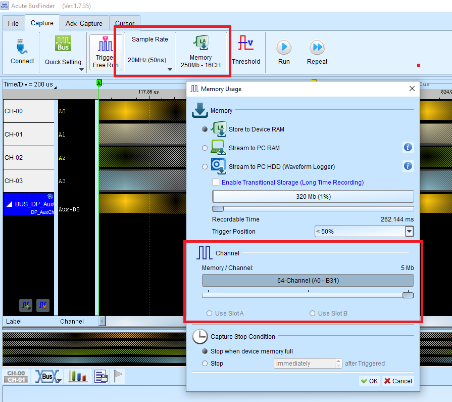
Appendix 1: Image Restoration Function
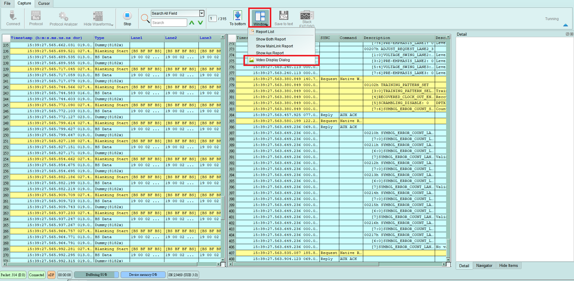
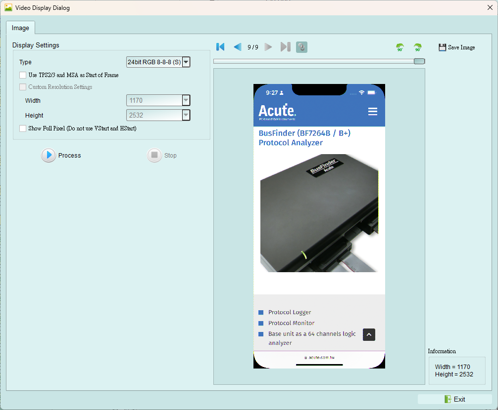
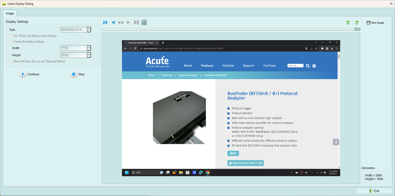
Click Window->Video Display Dialog to enable the image restoration function.
Set the eDP format and resolution sent by the object under test, or let them switch automatically based on the MSA packet, then click Process to start restoring the image. The dialog is also linked to the data in the main report area, which makes it easier to locate image data. Save Image can output the restored image in .jpg / .bmp / .bin format.
Setting Options:
**Type: **
It is necessary to set the format used by the object under test,
**Use TPS2/3 and MSA as Start of Frame: **
Under normal circumstances, MSA will be used as the beginning of the restored image. If the object under test is in a special state and some images do not send MSA, please check this item to restore it correctly. In addition , if this item is checked, Custom Resolution Settings will be forcibly turned on, and the resolution of the object under test must be set.
**Custom Resolution Settings: **
If checked, a custom resolution is used.
Show Full Pixel (do not use VStart and HStart): If checked, the VStart and HStart values of MSA are not applied, and only the raw data and MSA resolution are used to restore the image.
- Resolution - 1170 * 2532
- Resolution - 2880 * 1800
Appendix 2: Wiring example
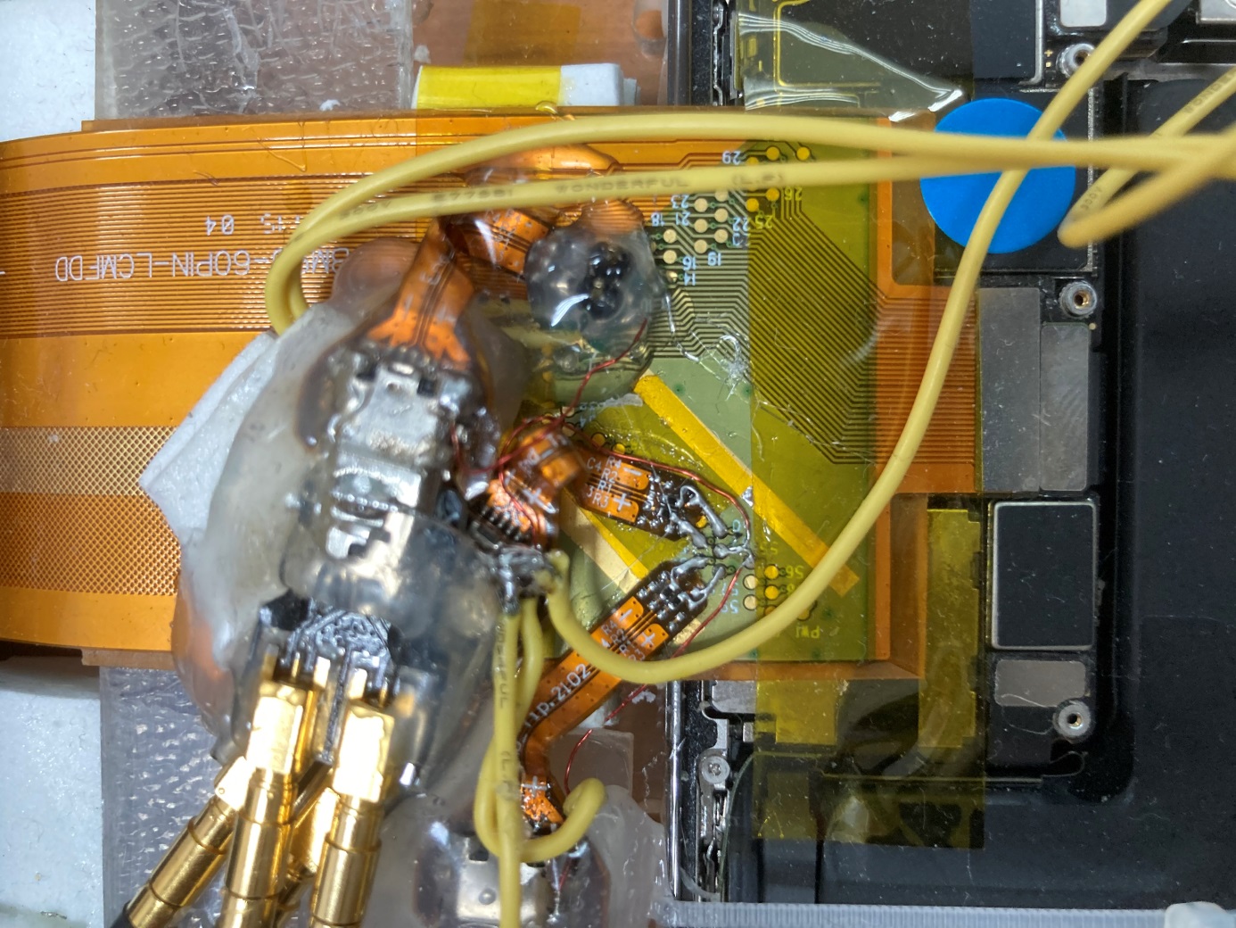
Use an end-tip to connect the DUT with a jumper. The jumper must be less than 5mm long. Each end-tip adds a ground to the SMPM connector to improve signal quality.
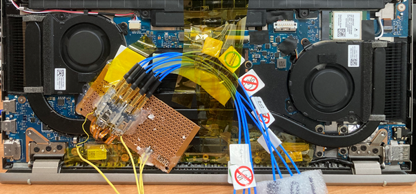
Example of Notebook Wiring
Appendix 3: eDP Waveform Detection Function:
- Steps:
- Connect the Positive of the Lane to be measured, turn on the protocol analyzer mode of eDP, and turn on the waveform display option.
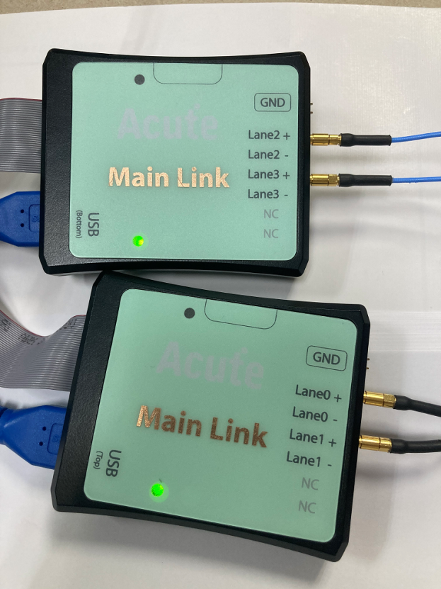
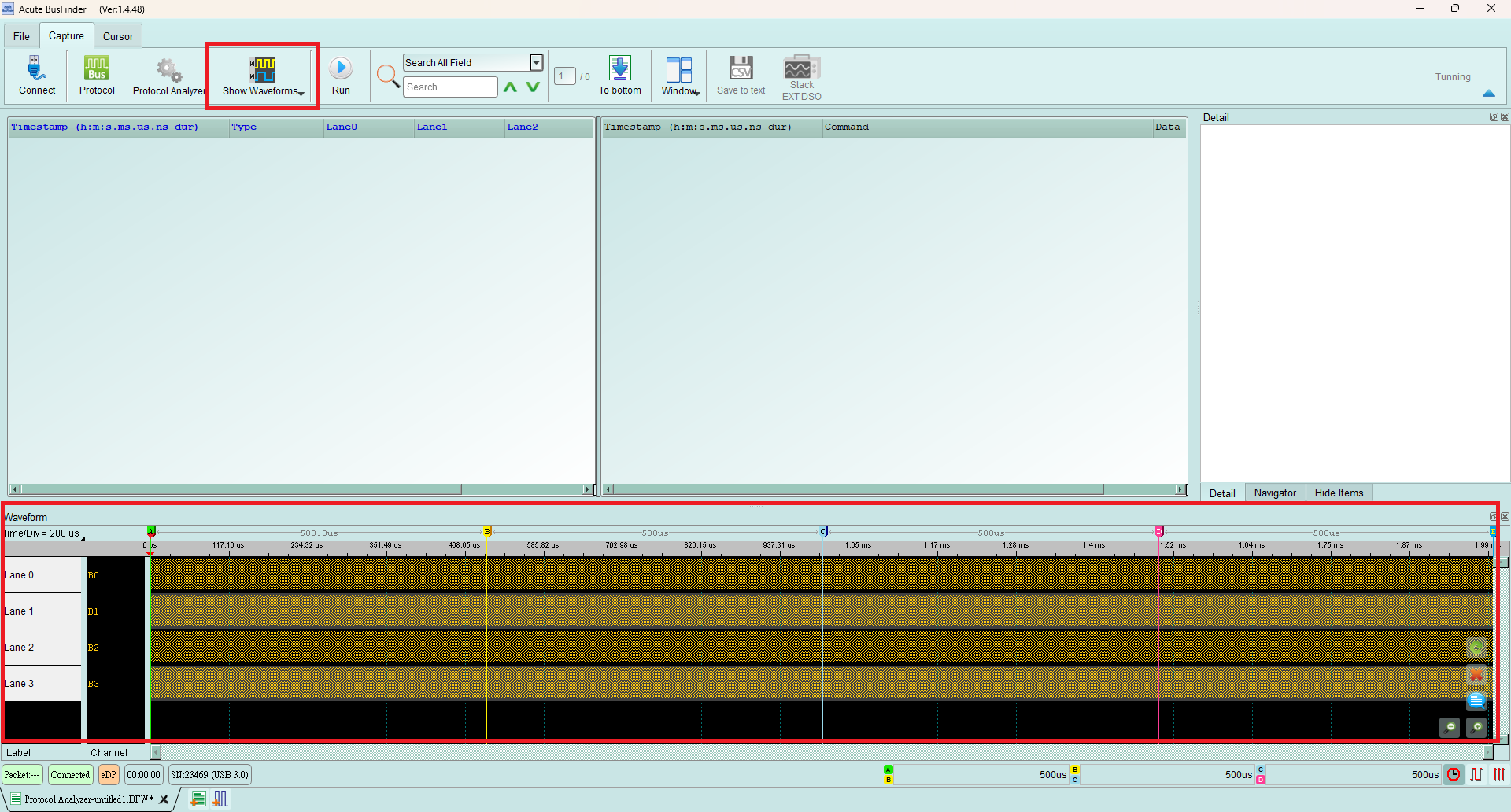
- Check whether there is a correct waveform
- (please see 2. Example of Waveform Display)
- Please remove the Positive and connect the Negative of Lane to repeat the action of step “a”.
- **Example of Waveform Display **
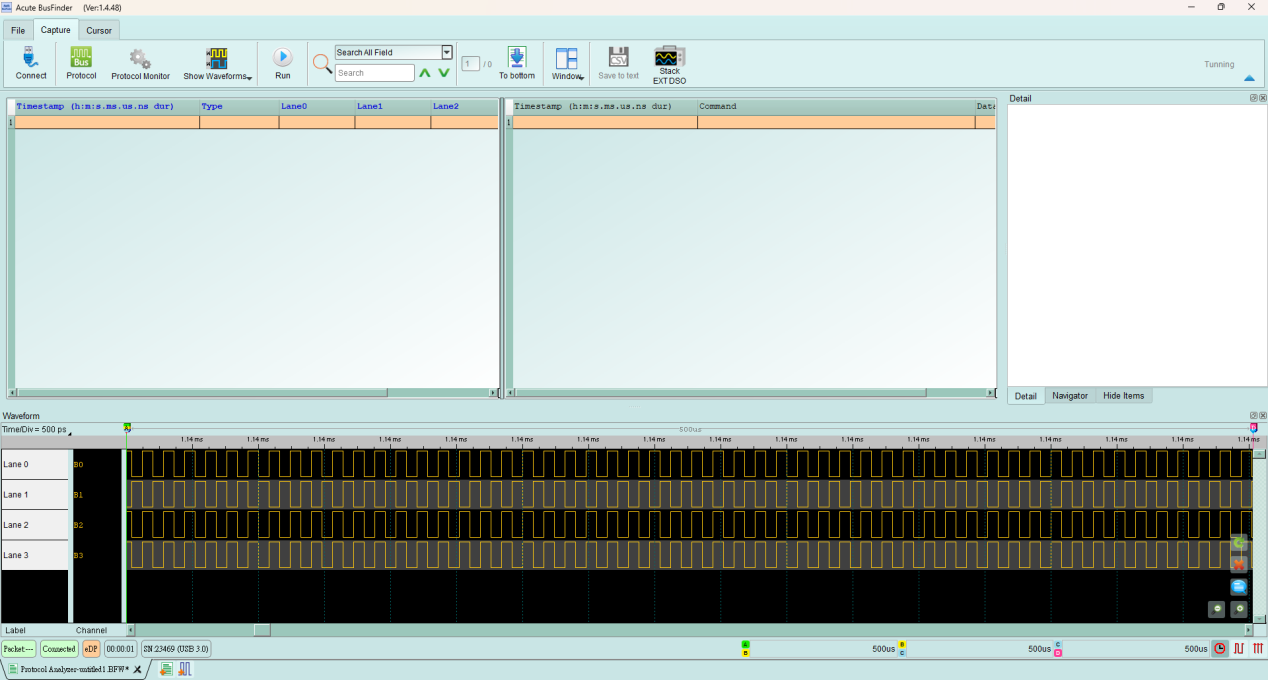
When there is no signal input, regular square waves will be displayed.
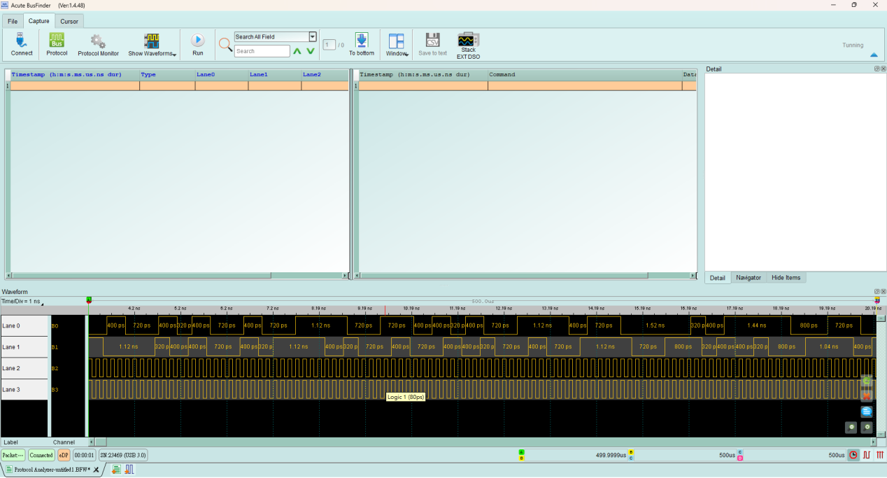
Waveform display with signal input, (Lane0, Lane1 has signal; Lane2, Lane3 has no signal) When there is signal, an irregular square wave will be displayed.