UFS (Universal Flash Storage)
UFS Protocol Analyzer settings. This feature is available only on selected BusFinder models.
For application notes, probe connection, and measurement details, see Protocol Solution — UFS.
Supported Models
BusFinder
| BF7264B | BF7264B+ | BF7264BPro |
|---|---|---|
| ● | ● |
This feature requires purchasing an additional option.
Settings
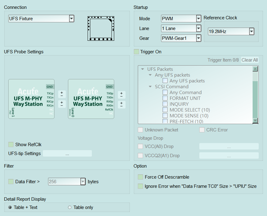
- Settings:
- Connection: Select how BF7264B+ / Pro connects to the DUT (for example UFS Fixture).
- Startup: Startup conditions of the DUT at capture time.
- Mode: Startup mode (for example PWM). Default: PWM.
- Lane: Number of lanes (for example 1 Lane / 2 Lane). Default: 1 Lane.
- Gear: Gear for the selected mode (for example PWM-Gear1). Default: PWM-Gear1.
- Reference Clock: Reference clock frequency (19.2 / 26 / 38.4 / 52 MHz). This value must be set correctly even if RefClk is not connected; otherwise analysis may fail.
- UFS Probe Settings: Probe / lane wiring settings.
- Way Station pinout for each lane (TX/RX p, n, RefClk, etc.); swap p/n per lane as wired.
- Show RefClk: Show RefClk measurement data in the result. Default: cleared.
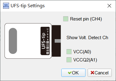
- UFS-tip Settings: Open the UFS-tip Settings dialog (see below) for tip pin options. Default: all items cleared.
- Reset pin (CH4): Enable UFS Reset pin detection. Reset must connect to UFS probe LA tip CH4; when Reset is seen, Power mode is reset to PWM mode.
- Show Volt. Detect Ch — VCC(A0) / VCCQ2(A1): Show tip voltage-detect channels A0 / A1 (VCC / VCCQ2; used with voltage-drop trigger — see Settings — Voltage Range Settings).
- Filter: With Data Filter enabled, the length field is enabled (Enable); drop trailing payload beyond the set byte length. Default: cleared (about 256 bytes when enabled).
- Option:
- Force Off Descramble: Skip descramble and show scrambled data only. Default: cleared.
- Ignore Error when 'Data Frame TC0' Size > 'UPIU' Size: Ignore that size mismatch error when checked. Default: checked.
- Detail Report Display: Detail report presentation. Default: Table only.
- Table + Text: Table plus textual decode.
- Table only: Table only.
- Trigger settings:
- Trigger On: Up to 8 trigger conditions. Main Default does not reset the trigger list.
- Unipro / UFS packets, SCSI Command items (for example Any UFS packets or a specific SCSI command).
- Unknown Packet / CRC Error: Trigger on unknown packets or CRC errors.
- VCC(A0) Drop / VCCQ2(A1) Drop: Voltage-drop trigger; open Voltage Range Settings (see Settings — Voltage Range Settings). Typical VCC about 2.70–3.60 V, VCCQ2 about 1.70–1.95 V.
- Clear All: Clear configured triggers.
- Trigger On: Up to 8 trigger conditions. Main Default does not reset the trigger list.
Open this dialog from UFS Probe Settings → UFS-tip Settings. The left side shows the tip pinout (including CH4 / A0 / A1). Enable Reset pin (CH4) and, under Show Volt. Detect Ch, VCC(A0) / VCCQ2(A1) as needed. Dialog Default: all items cleared.