NAND Flash
Feature:
Supported Models:
| BF6264B | BF7264B | BF7264B+ | BF7264 Pro |
|---|---|---|---|
| ● | ● | ● | ● |
BF7264B/B+/Pro has two USB holes at the front.
Specifications:
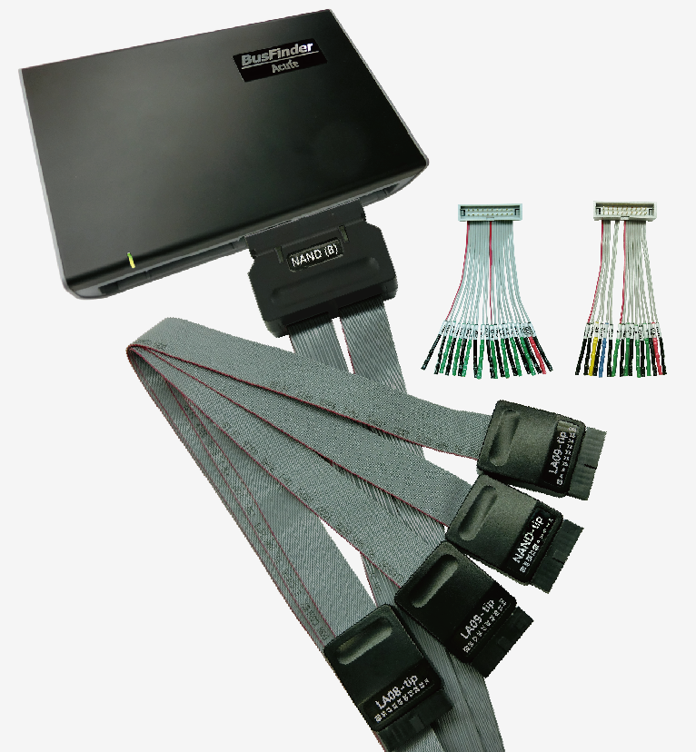
- BF7264B/B+/Pro, 32Gb RAM, NAND Flash probes
- Supports ONFI 4.1 (NV-DDR3), Mode 8 / Toggle DDR 2.0
- ~267 MHz

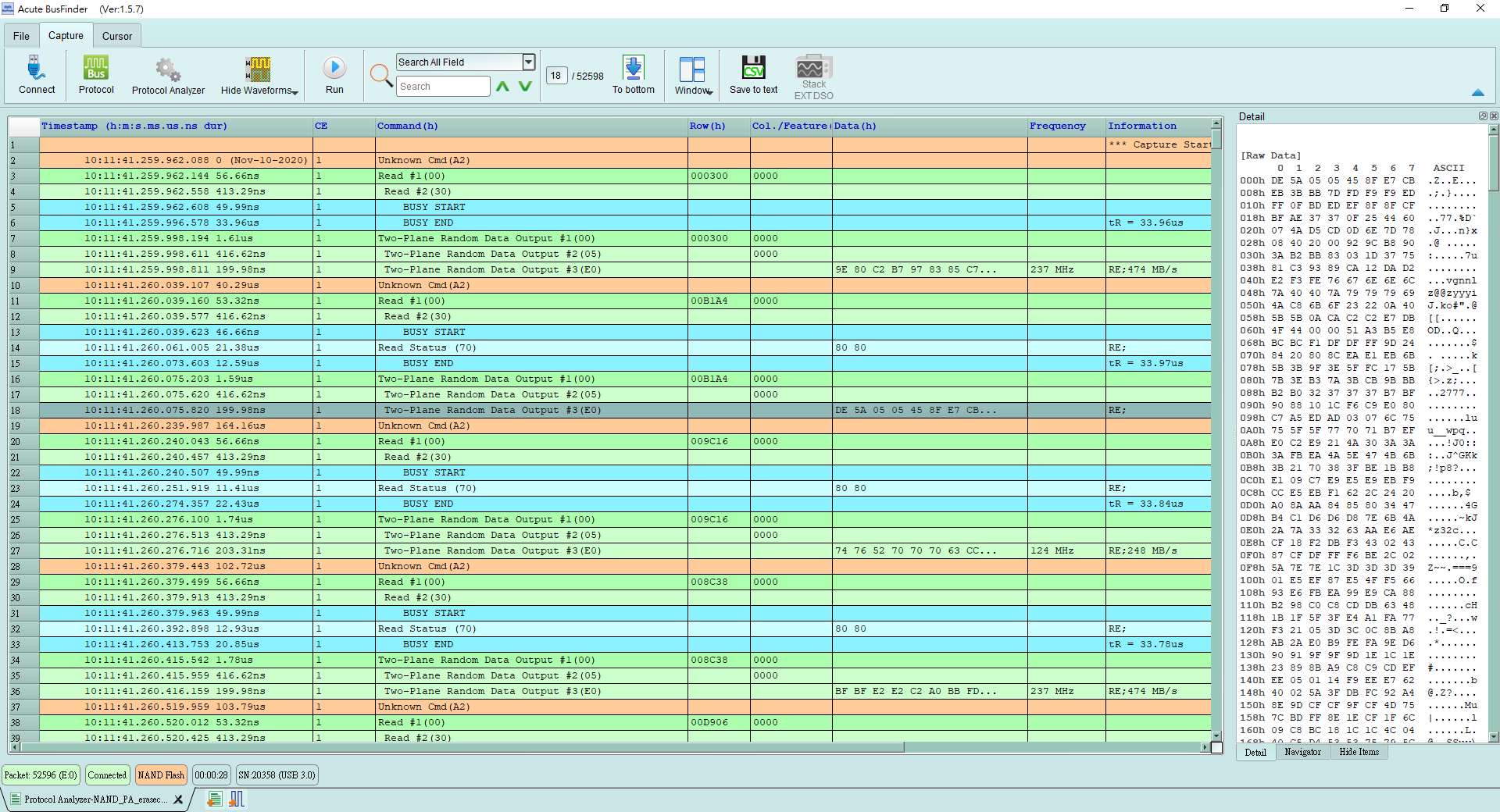
- Display NAND Flash protocol packet in tabular form, including command parsing
- Use 32Gb RAM as the buffer to stream all NAND Flash data into the SSD HD in order to record all data flow from low speed mode to high speed mode.
- Data Filter function filters unwanted data to save memory.
- Search function searches for specific data.
- Erase Count function counts how many times a block has been erased.
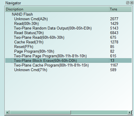
- NAND command statistics include the number of packets and per-command counts.
6. NAND trigger
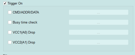
- Trigger parameters include commands and data in order to cover all kinds of packets.
- Trigger Command/Address/Data
- Busy Time Check
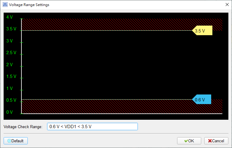
- VCC1 drop and VCC2 drop
- The Trigger-Out port is to trigger a DSO to capture waveform.
-
Report area
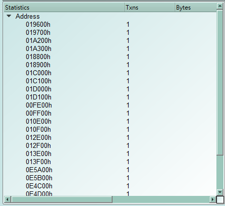
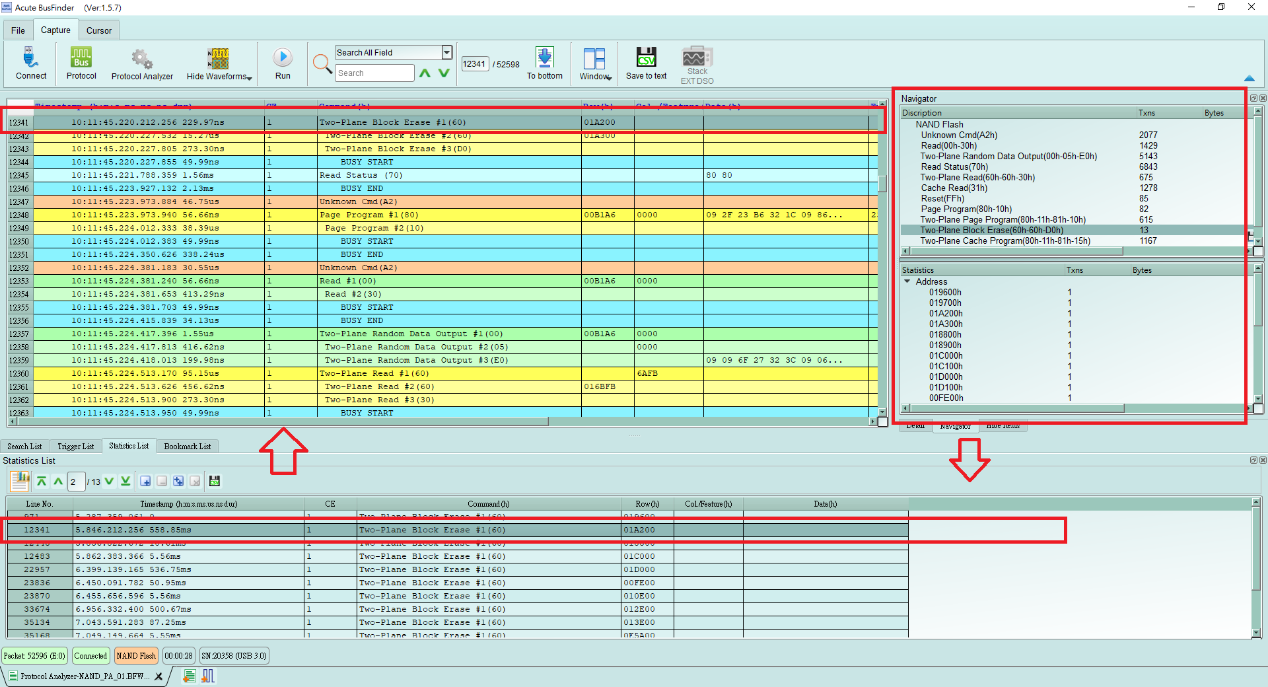
Statistics list: Quickly categorize and track the location of data with statistical functions.
- NAND Settings
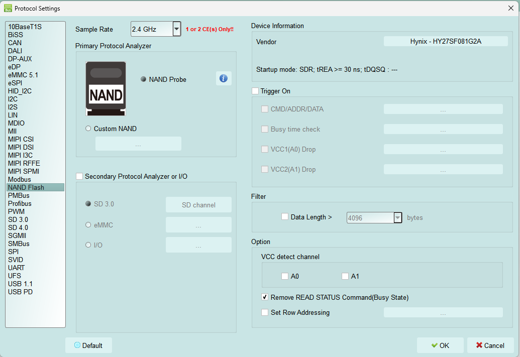
- Sample Rate: Choose the sampling rate to use. To enable the Secondary Protocol Analyzer – SD 3.0 or eMMC option, the sampling rate must be set below 1 GHz.
- Primary Protocol Analyzer: Can choose to use the probe type, or also customize the channel / trigger level.
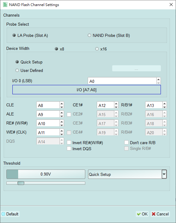
- Invert RE#(W/R#) / Invert DQS
- This function is used to measure at DDR mode. Since RE or DQS is a pair of differential signals, it needs to be checked if it is connected to another signal like RE(W/R) or DQS#. To tell the software that it is connected to the reverse RE and DQS signal.
- Don’t care R/B
- Check to ignore the R/B signal, which means that users don’t need to connect the R/B signal.
- Single R/B# At the Multi-CE measurement, the busy time is displayed from the polling
of Read Status command when checked; from R/B signal when unchecked.
- Secondary Protocol Analyzer or I/O: An additional set of specified logic
- analysis can be opened to analyze the remaining available pins at the same
- time.
- Vendor: Choose the NAND Flash brand and model. If there is no suitable model to choose from, you can choose the Custom item to customize the NAND Command Set. There is a sample fie in the working directory of the software; you can press the Edit button to edit. After editing, press Refresh to refresh the list. Finally, select the NAND Flash you want to use and press OK.
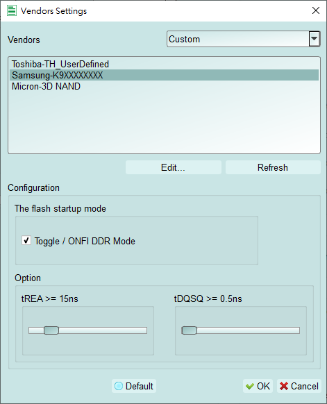
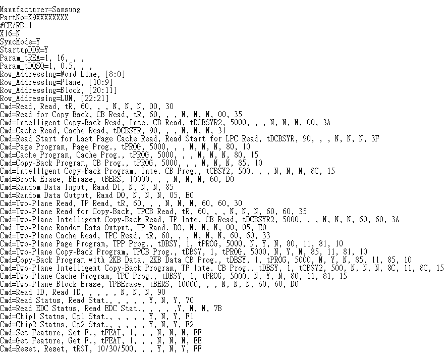
Manufacturer, PartNo, #CE/RB, X16, SyncMode, StartupDDR, Param_tREA, Param_tDQS, Row_Addressing, Cmd represent keywords, which must be entered and cannot be modified. The instructions are as follows:
| Keyword | Instructions |
|---|---|
| Manufacturer | NAND Flash vendor |
| PartNo | NAND Flash IC model |
| #CE/RB | The CE/RB set , only 1/2/4 can be input |
| X16 | Use 8 or 16 data channels, only Y/N can be input, Y means 16 channels are used; N uses 8 channels. |
| SyncMode | Only Y/N can be input, Y: supports synchronization mode; N: does not support synchronization mode. |
| StartupDDR | To tell the SW is at DDR mode |
| Param_tREA/Param_tDQS | Set the delay time for Data Out reading. |
| Row_Addressing | Default parameters of Set Row Addressing function |
| Cmd | The contents of command are separated by commas, and are explained as follows: |
| Cmd | 1. The full command name |
| Cmd | 2. Abbreviated instruction name |
| Cmd | 3. Name of the first group of Busy Time Check. If not, fill it out. |
| Cmd | 4. The first set of Busy Time Check values. The unit is us. If not, fill it out. |
| Cmd | 5. Name of the second group of Busy Time Check. If not, fill it out. |
| Cmd | 6. The second set of Busy Time Check values. The unit is us. If not, fill it out. |
| Cmd | 7. The first flag. This flag represents whether the command can be used in the Busy state. |
| Cmd | 8. The second flag. The flag represents whether the instruction is allowed to be inserted by some specific instructions. |
| Cmd | 9. The third flag. This flag represents whether the instruction is allowed to be inserted into certain multi-level instructions. |
| Cmd | 10. Command value. You can fill in 1-4 command codes, separated by commas. |
e.g.
Cmd=Read, Read, tR, 60, , , N, N, N, 00, 30
Cmd=Read Status, Read Stat., , , , , Y, N, Y ,70
Cmd=Two-Plane Page Program, TPP Prog., tDBSY, 1, tPROG, 5000,
N, Y, N, 80, 11, 81, 10
Read Status / Two-Plane Page Program: The full command name.
Read Stat. / TPP Prog. : Abbreviated instruction name.
Busy Time check (tDBSY, 1, tPROG, 5000) : It means that tDBSY is 1us, tPROG is 5000us, and if Busy Time exceeds this value, the information will be displayed in the report window. If this value is not filled in, the Busy Time will not be checked. Please enter a blank and add a comma at this time, the string of tDBSY or tPROG is not fixed and can be defined by the user.
Flags: Taking Cmd=Read Status, Read Stat., Y, N, Y, 70 as an example, the first flag is Y to indicate that the command can be used in the Busy state, and the second flag is N to indicate that the command is not allowed to be Some specific instructions are inserted, and the third flag is Y, which means that the instruction is allowed to be inserted into some multi-level instructions. For example, Read Status 70h can be inserted between 11h and 81h of Two-Plane Page Program 80h, 11h, 81h, 10h.
- Trigger on: Set CMD/ADDR/DATA, Busy time check, and Voltage drop trigger conditions.
- Filter: Each data frame can specify a record size; data larger than the set value is not recorded.
- Other option:
- 2 sets of voltage detection
- Remove READ STATUS Command (Busy State)
- When enabled, the repeated Not Ready polling of the Read Status command is removed. It is checked by default; otherwise it takes up too many report lines and is hard to read.
- Set Row Addressing
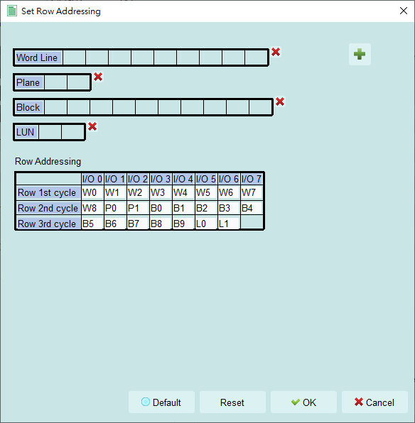
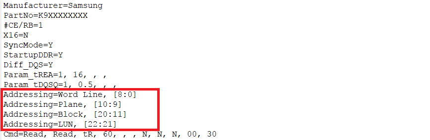
This function is mainly used to subdivide Row Address into Page Address, Word Line, Plane Address, Block Address, LUN Address... The default value will be created in the NAND Command Set table, as shown in the red box in the figure below:
- The Row Address Details will be displayed in Details when this function needs to be turned on, and it is turned off by default.
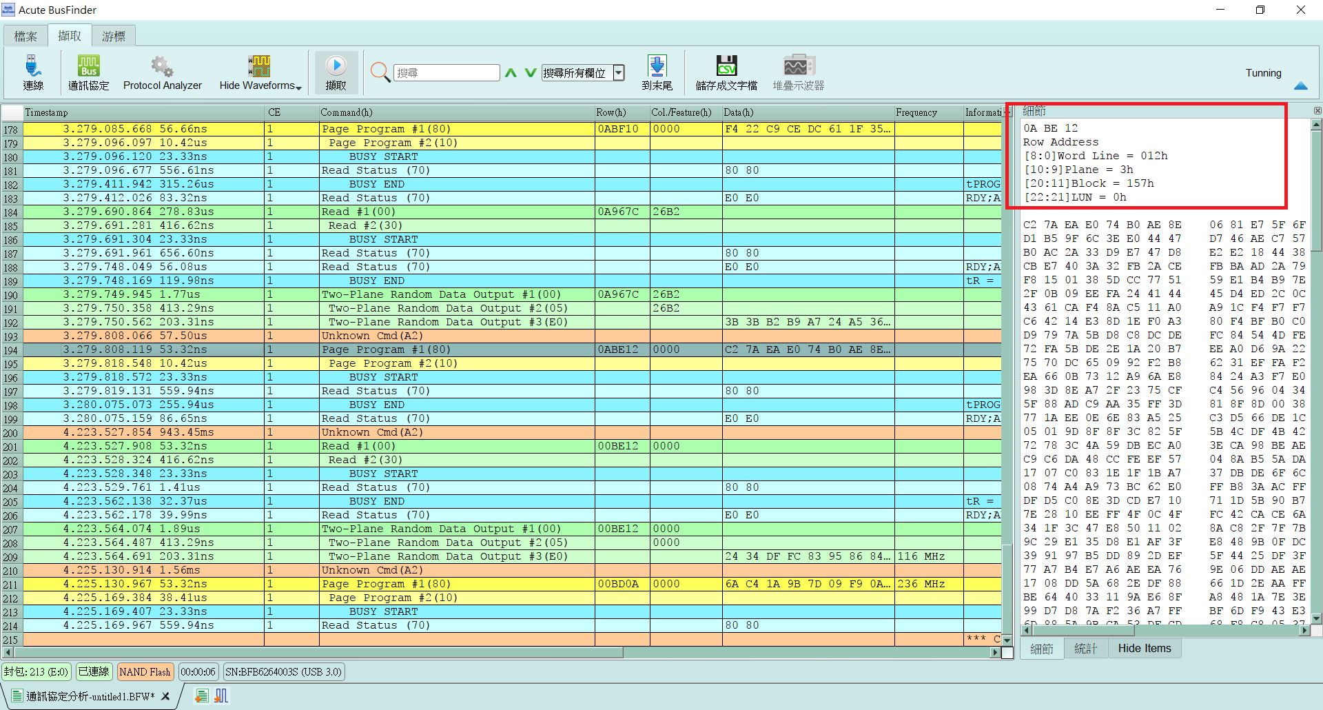
- Because the customer's NAND Flash model may not be supported, the UI also provides the function for customers to input by themselves, and can add/delete the items above.
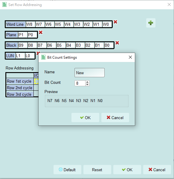
Items can be dragged from the top to set the bits to the Addressing table below
- Or when the lower yellow box appears, you can directly click on the upper Items to automatically return to the lower yellow box.
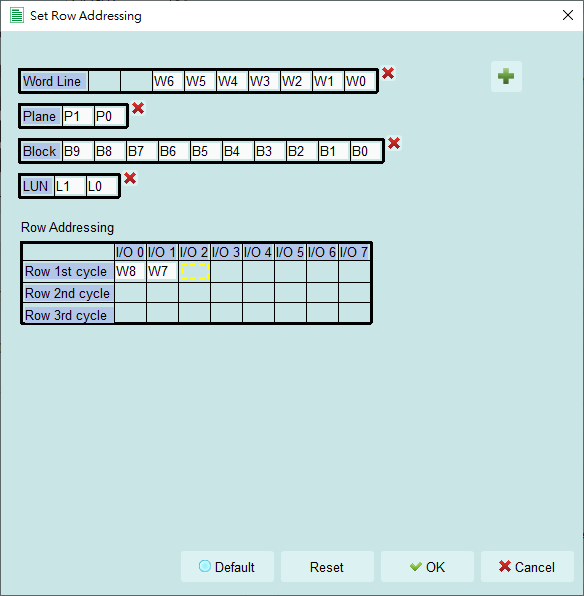
Remarks:
Report background color description:
-
When NAND read command, 1st Command displays green, and after 2nd Command displays light green.
-
When the NAND program command is used, the 1st Command is yellow, and the 2nd Command is light yellow.
-
Unknown command will be displayed in orange.
-
Other commands will be displayed in light blue.
FAQ
-
Which version of NAND Flash specification does it support? A: ONFI 4.1 (NV-DDR3), Mode 8 / Toggle DDR 2.0, although the specification speed is about 267 MHz, the BF series products support a maximum speed of 300 MHz.
-
Will it affect the signal quality during measurement?
- A: The external instrument measurement will inevitably have a partial load effect. We use the active probe connection method to reduce the interference of the object to be measured and improve the signal quality.
- Does it support for the transmission function?
- A: No.
- Precautions during measurement
- A: Make the connections as described in "Probe and test object connection" on page 17.
- Can I specify a NAND Flash command as the trigger point A: Yes, you can input a specific NAND Flash command value to trigger.
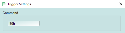
- Is it possible to set a NAND Flash command starting point and specify how much time to capture data?
- A: You can set the starting condition to the trigger item and adjust to the data
- monitor mode in the working mode menu. And specify the length of acquisition
- time.
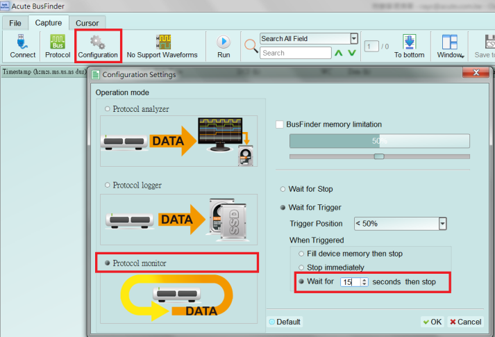
- How to know whether the NAND Flash is connected correctly?
- A: It is recommended to capture the Read ID command waveform to confirm
- whether the connecting is correct.
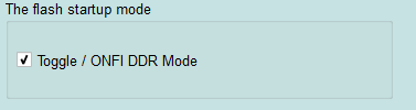
- What happens when the program command is given but the software analysis is empty of NAND Flash data in?
- A: To confirm that the connecting is correct, and check whether it has entered the
- DDR mode, if it entered the DDR mode, you can check the Toggle/ONFI DDR
- Mode.
Probe and test object connection
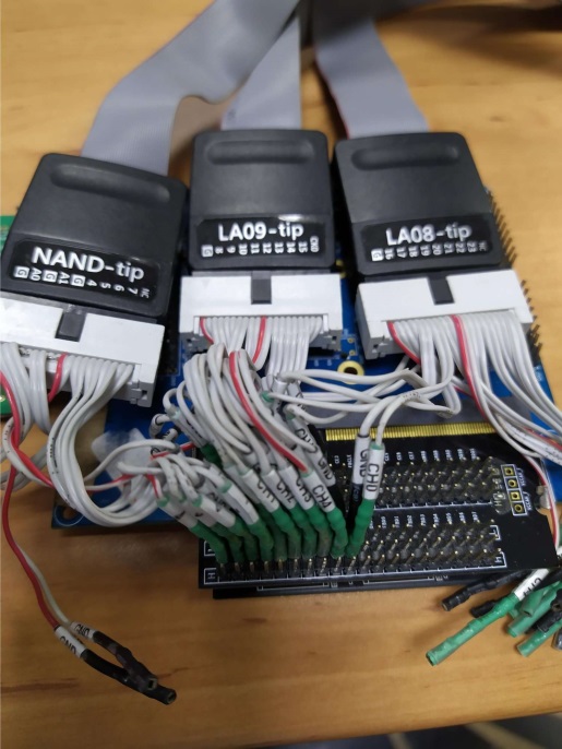
With a flying-lead cable connection, the more ground wires you connect, the better the signal quality.
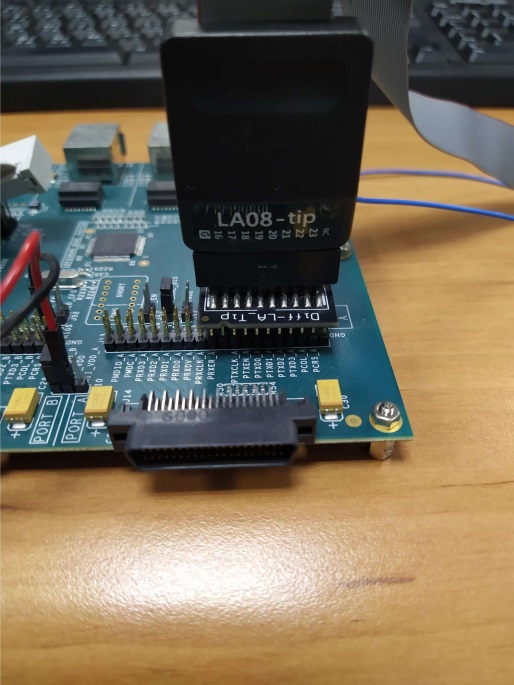
A direct tip connection gives the best signal quality. This picture is only a schematic and does not show a real NAND Flash DUT connection.