eMMC
Feature:
Supported Models:
| BF6264B | BF7264B | BF7264B+ | BF7264 Pro |
|---|---|---|---|
| ● | ● | ● | ● |
BF7264B/B+/Pro has two USB holes at the front.
Specifications:
- BF7264B/B+/Pro, 32Gb RAM, eMMC 5.1 probes
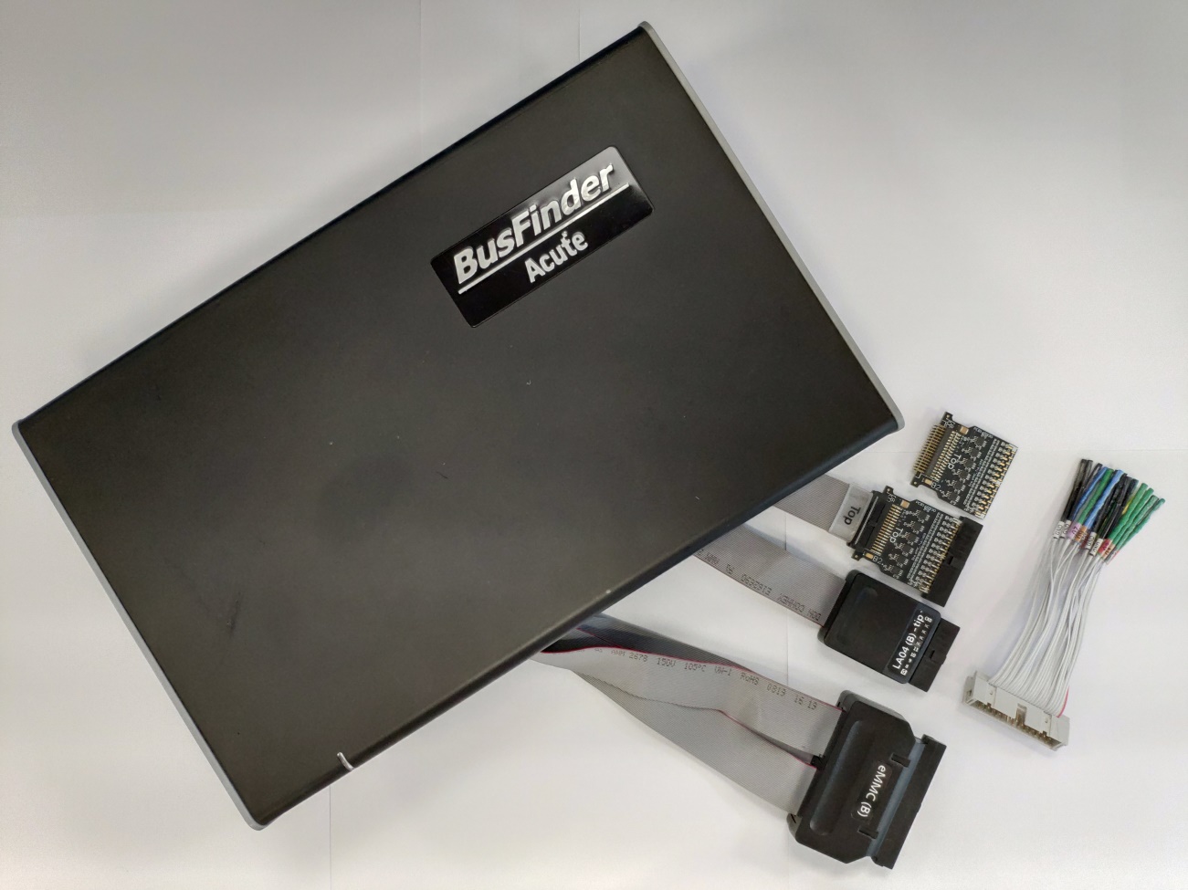
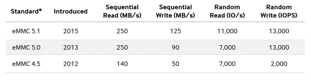
- Supports eMMC 5.1 Up to eMMC 5.1 HS400
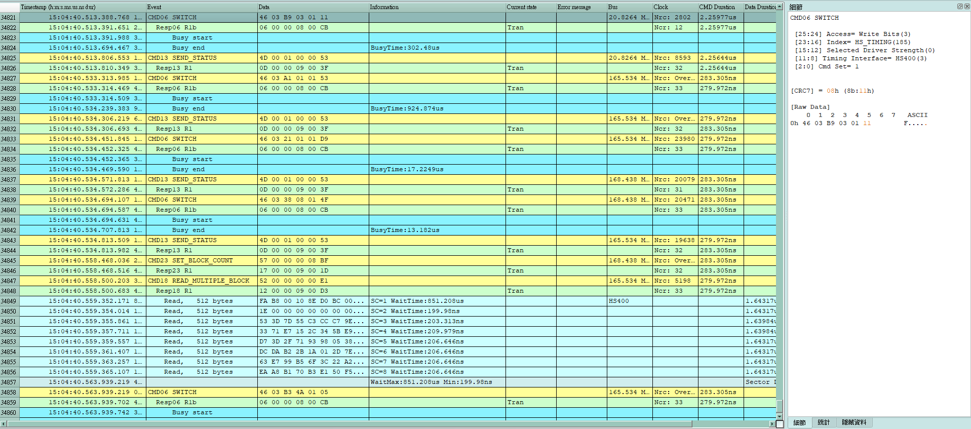
Can display eMMC protocol packet data in tabular form, including command parsing
- Use 32Gb RAM as the buffer to stream all eMMC data into the SSD HD in order to record all data flow from Low Power Mode to High Speed Mode.
- “Data Filter” filters unwanted data to save memory.
- “Search” searches specific data.
- “CRC Packet” displays and counts CRC
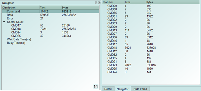
- eMMC command statistics include numbers of packets, individual command, different data length, and errors
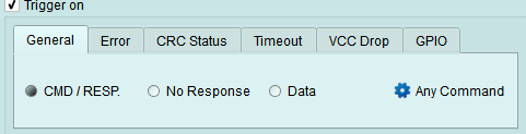
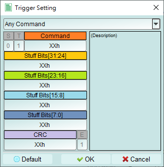
- eMMC command trigger
- Trigger parameters include commands and data in order to cover all kinds of packets.
- Command or 16 byte Data.
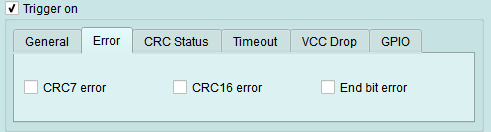
- CRC7, CRC16, End Bit Error.
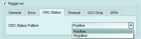
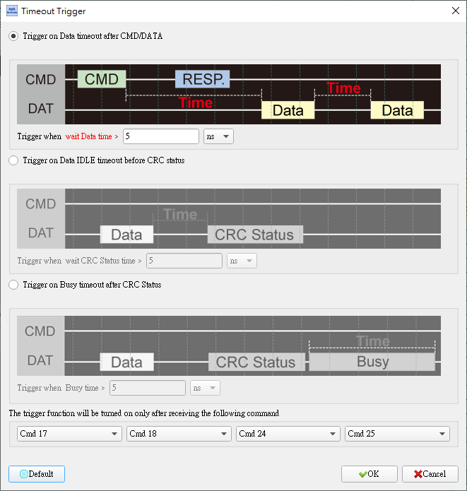
- Data to Data timeout, CRC Status timeout, CRC Status pattern, Busy timeout.
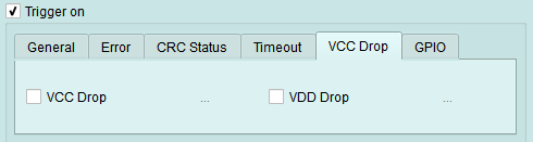
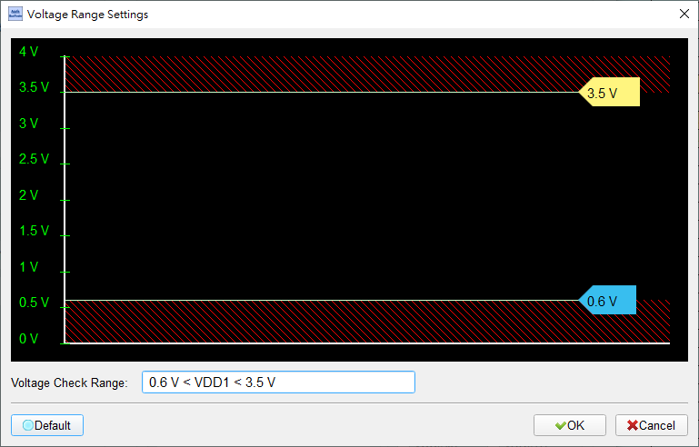
- VCC drop, VCCQ2 drop.
- The Trigger-Out port is to trigger a DSO to capture waveforms.
-
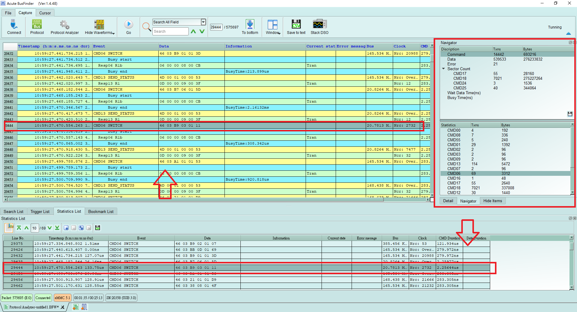
Report area
Statistics list: Quickly categorize and track the location of data with statistical functions.
- eMMC settings
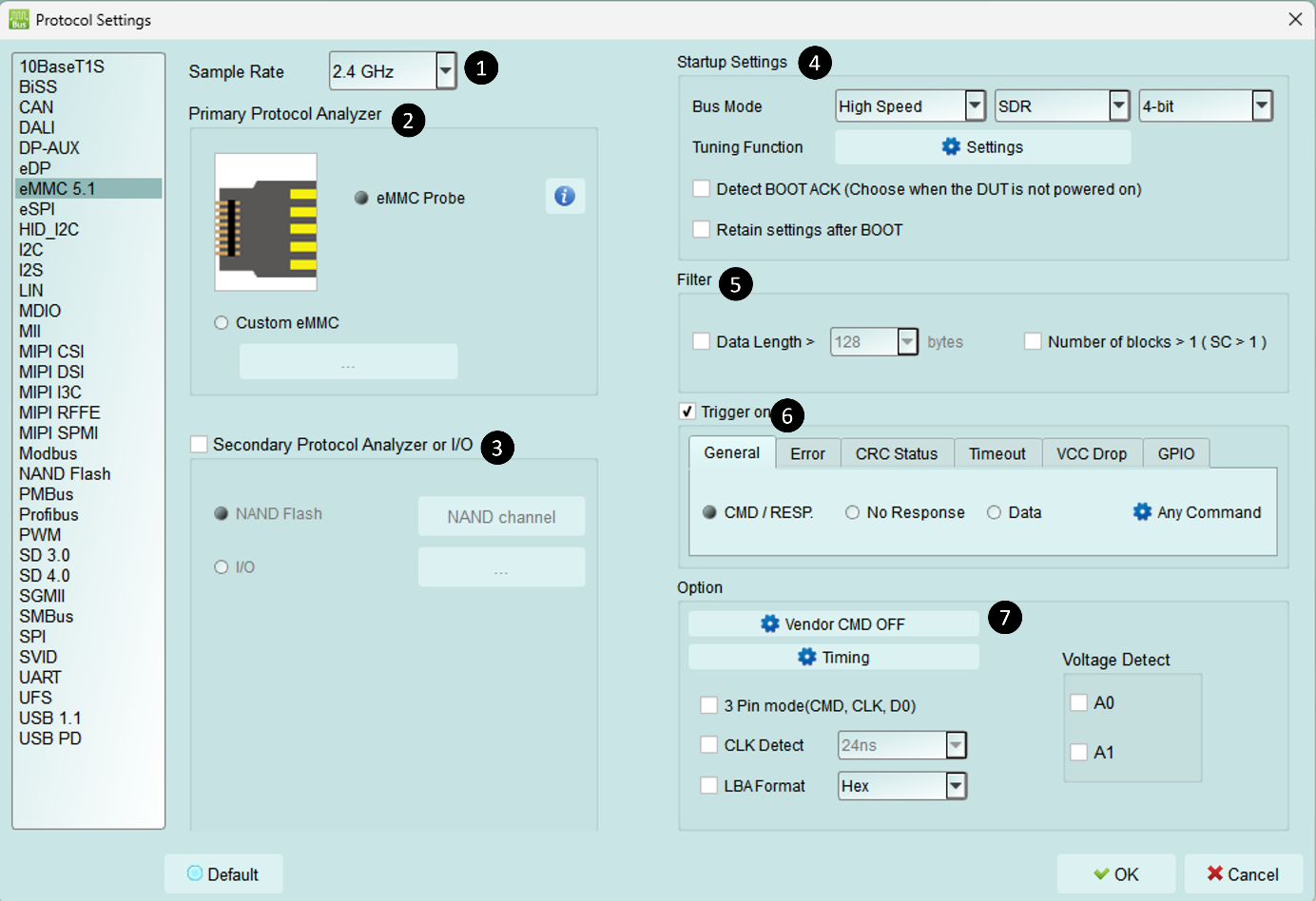
- Sample Rate: Choose the sampling rate. To enable the Secondary Protocol Analyzer – NAND Flash option, the sampling rate must be set below 1 GHz.
- Primary Protocol Analyzer: Choose the probe type, or customize the channel and trigger level.
- Secondary Protocol Analyzer or I/O: Open an additional logic analysis set to analyze the remaining available pins at the same time.
- Startup setting: Set it to the mode of the current capture, matching how the device under test is running. It also has a Tuning function.
- Filter: Each Data Frame can specify a capture size; data larger than the set value is not recorded.
- Trigger on: You can set CMD, DATA, ERROR, Voltage, Timeout, and CRC Status trigger conditions.
- Other options:
- Vendor CMD: Rename the command group yourself, with or without extra information.
- Timing: Set the number of clock cycles per symbol.
- 3 Pin mode: After connecting CLK, CMD, and D0, you can analyze the protocol flow and status. Mainly used for devices with difficult wiring or non-data errors.
- CLK Detect: Detect whether CLK is active.
- Two sets of voltage detection
FAQ
- What eMMC version is supported?
- A: Support eMMC 5.1 HS400 / HS200 / CMD Queue.
- Will the signal quality be affected during measurement?
- A: The measurement of the external instrument will inevitably have some load effect. We use the active probe to reduce the interference of the object to be measured and improve the signal quality.
- Is Tx supported?
- A: No
-
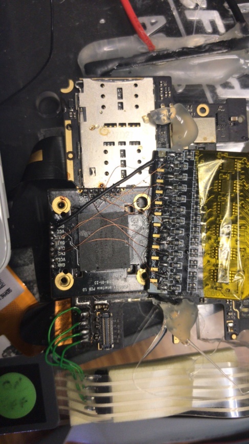
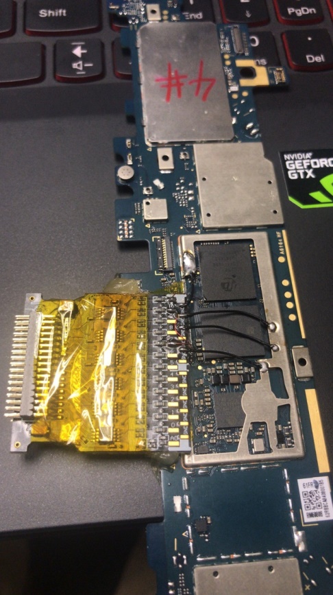
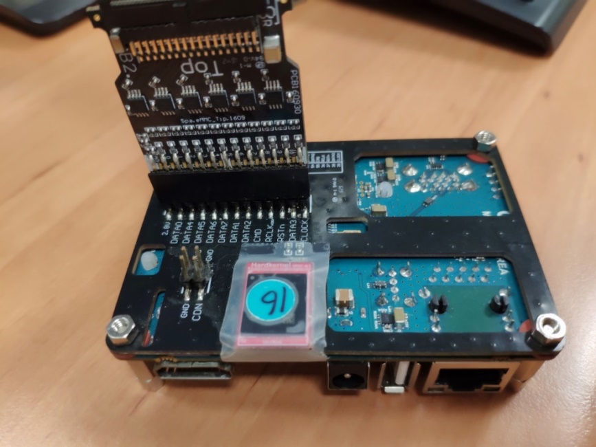
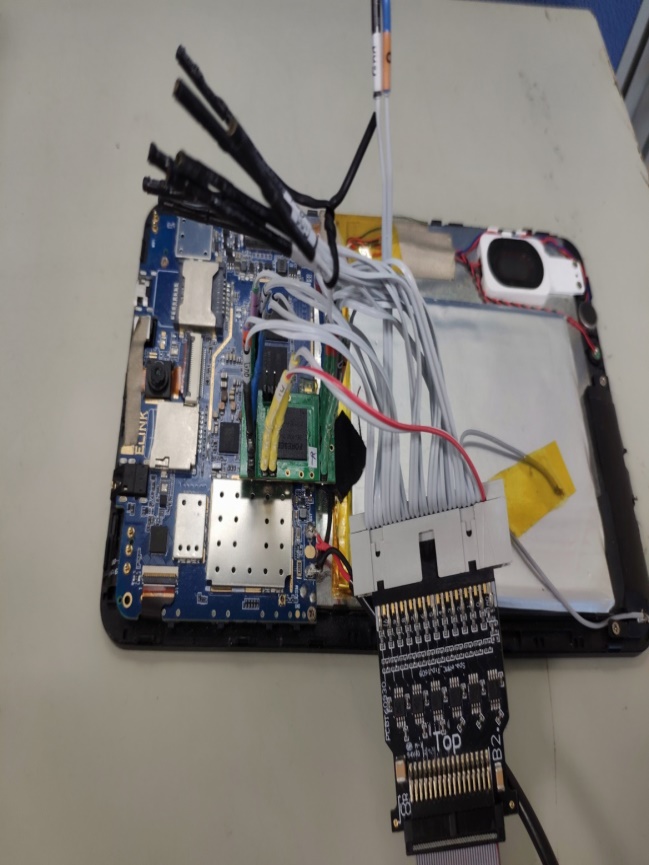
Precautions during measurement Make the connections as described in "Probe and test object connection" on page 9.
-
Can I specify an eMMC packet as the trigger point function?
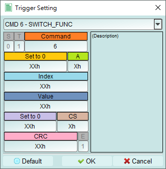
A: You can specify specific eMMC packet or Error to trigger.
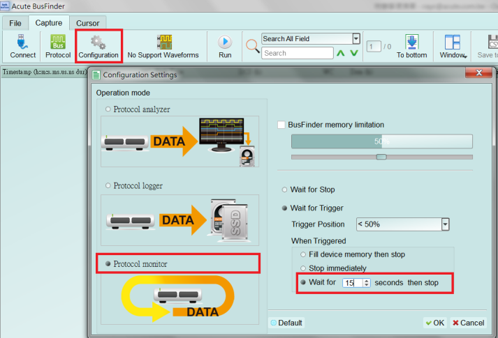
- Is it possible to set an eMMC starting point, and specify how much time to capture Data?
- A: You can set the starting condition to the trigger item and adjust to the data monitor mode in the working mode menu. And specify the length of acquisition time.
- Secondary Protocol Analyzer or I/O
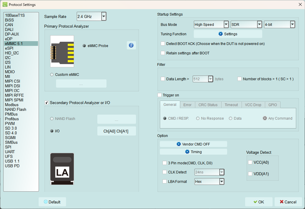
- While using the eMMC 5.1 protocol analyzer, you can additionally enable the NAND Flash logic analyzer function or additional I/O pins for analysis.
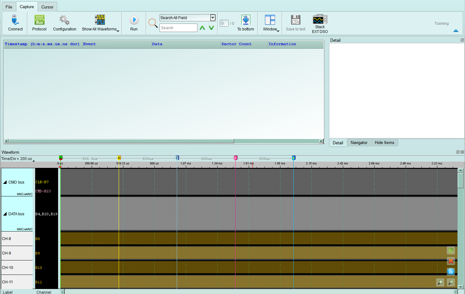
To use this function, turn on "Show Waveform" on the main screen of the protocol analyzer.
- Since the analysis of NAND Flash requires the use of more channels, an LA probe needs to be connected to Slot A, and it can only be turned on using a sampling rate of 1GHz.
BusFinder and Probe connection
The BusFinder can only use Slot B as the probe connection slot.
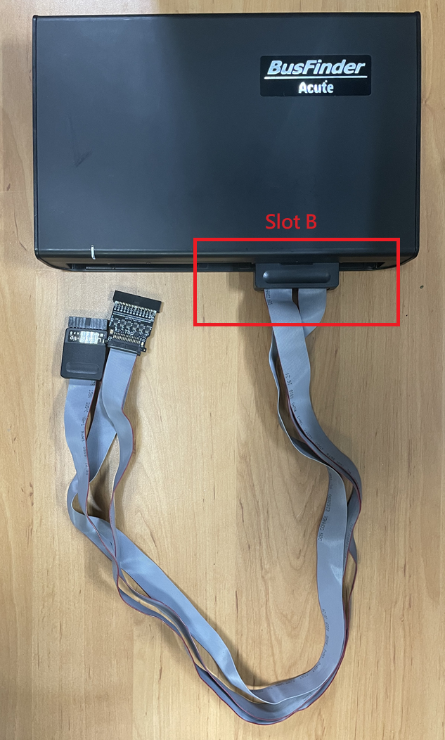
Probe and test object connection