Power Sequence Validation
Note
This feature is not supported on TravelBus series products.
Overview
In the previous sections, we introduced Waveform Statistics and Cursor for you to perform measurement analysis on your captured data. With both tools, we can apply to various applications within debugging.
This is important in modern electronic systems. Some use cases such as:
- Power On/Off sequence verification on motherboards
- Repeated measurement sequences
- Design verification
In this section, we will introduce how to further add restrictions on these measurements to ensure these timing meets our requirements, to ensure the step-by-step power sequence of supplying and removing power to the components are correct and prevent from damage.
Step-by-step workflow
-
Find the
Timing Checkbutton in the Adv. Capture tab of the toolbar and click it to open the timing check dialog.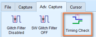
-
Choose the configuration (.csv) file you want to use for.
- Choose which mode to enter, either Timing Check or H/W Strap.
- After the configuration is set, start the capture by clicking the Start button.
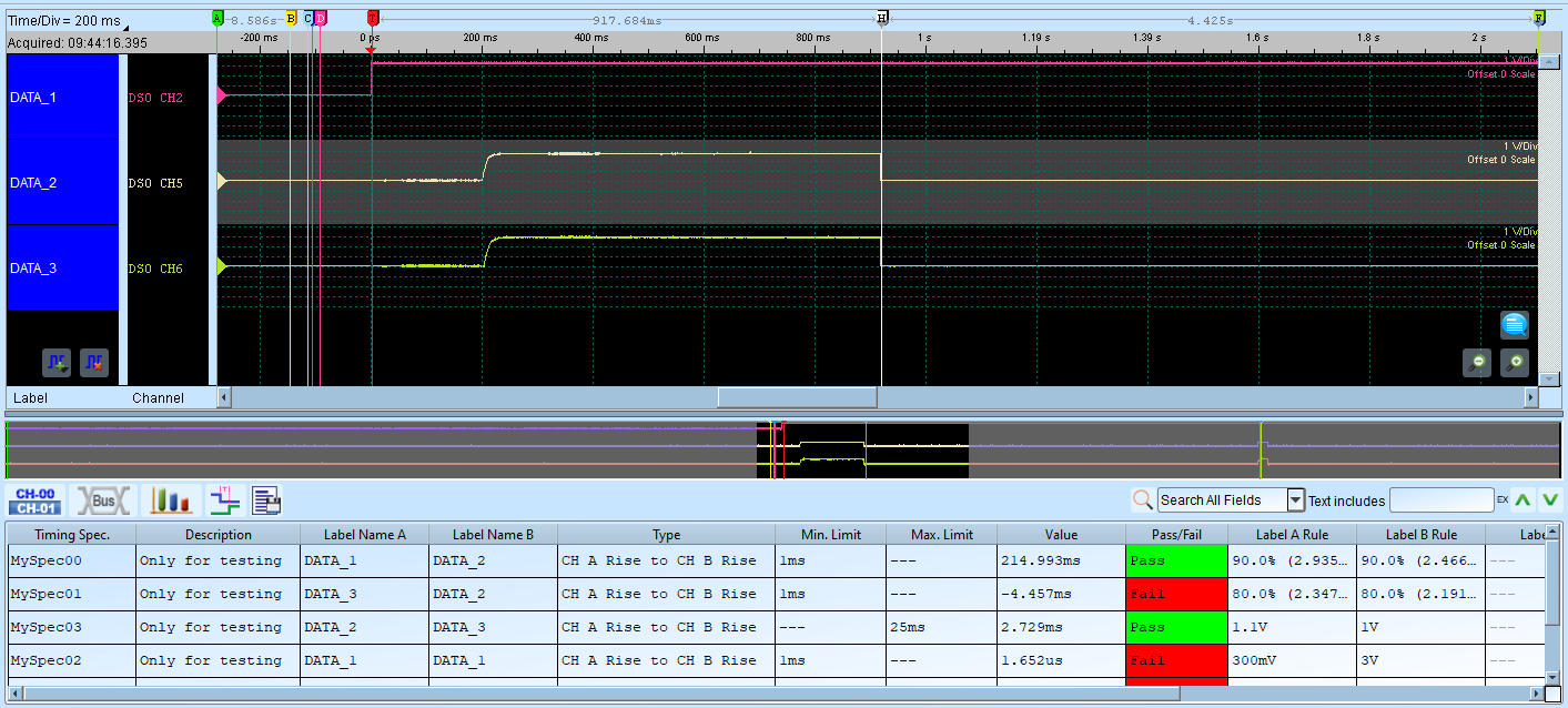
- Once finished, the software will analyze the results and display the Pass/Fail status for each measurement.
A snapshot of the timing check report is shown below:
Configuration File Format
Here we start defining how we construct the configuration file. The configuration file is in CSV format and is composed of multiple sections, which define the capture settings we need.
Configuration file format requirements
- Field names at the beginning of each section
- Comma-separated values
- Semicolon (;) at the end of each section
- Comments after double slash (//) are ignored
Valid format examples:
1 2 3 | |
1 2 3 | |
If you need sample files for reference, please contact us at service@acute.com.tw.
Configuration Cheat Sheet
SampleRate
Input the sample rate value, Units: MHz, KHz, Hz.
Example:
1 2 3 | |
Note
The maximum sampling rate range that can be used will be affected by the number of channels and trigger types. The minimum sampling rate cannot be lower than 100 kHz.
If SampleRate is set, both AnalogSampleRate and DigitalSampleRate will be set to the same value.
AnalogSampleRate
Note
This configuration is only available for Mixed-Signal Oscilloscope series.
Input the analog sample rate value, Units: MHz, KHz, Hz.
Example:
1 2 3 | |
DigitalSampleRate
Input the digital sample rate value, Units: MHz, KHz, Hz.
Example:
1 2 3 | |
ChannelNumber
Note
This is only available for TravelLogic series.
Note
The number of channels available will vary depending on the sample rate and whether transitional storage mode is enabled/disabled.
Specify the number of channels to use.
| Sample rate | LA Non-Transition | LA Transition |
|---|---|---|
| 2 GHz | 0:3 (4 channels) | 0:2 (3 channels) |
| 1 GHz | 0:7 (8 channels) | 0:5 (6 channels) |
| 500 MHz | 0:15 (16 channels) | 0:11 (12 channels) |
| 250 MHz, 200MHz | 0:31 (32 channels) | 0:23 (24 channels) |
Example:
1 2 3 | |
RecordLength
Set the recording memory depth. Units: MB, Mb.
The maximum recording memory depth depends on the different models. The value cannot be lower than 16 Mb.
Example:
1 2 3 | |
TransitionalMode
Enable or disable transitional storage mode.
Set to 1 to enable transitional storage mode, 0 to disable.
Example:
1 2 3 | |
Note
This is ignored when analog channels are used with Mixed-Signal Oscilloscope series.
Threshold
Configure voltage thresholds for logic level detection. Unit: mV or V.
For TravelLogic series, the voltage threshold range is ±5V.
For Mixed-Signal Oscilloscope series, the voltage threshold range is ±20V.
Example:
1 2 3 4 5 6 | |
Note
For TravelLogic series, when the Schmitt circuit function is enabled, Channel 16-31 will turn into the secondary reference threshold voltage. Mixed-Signal Oscilloscope series are not affected.
UseSchmittCircuit
For TravelLogic series, set to 1 to enable Schmitt circuit function, 0 to disable. This will affect the significance of the parameters of the voltage level, and the maximum number of available channels will drop to 16 channels.
For Mixed-Signal Oscilloscope series, this parameter is used to enable hardware Schmitt circuit hysteresis function, and the number of available channels will not be affected.
Example:
1 2 3 | |
Hysteresis
Note
This parameter is only available for Mixed-Signal Oscilloscope series.
Enable or disable hardware Schmitt circuit hysteresis function. Set to 1 to enable, 0 to disable.
Example:
1 2 3 | |
Channel
Channel configuration and their properties respectively. Columns are defined as follows:
- Channel selection:
CH0(for digital channel 0),CH(A)0(for analog channel 0) - Label name: Up to 31 alphanumeric characters
- Mode (optional): TimingCheck, HwStrap, or TimingCheck+HwStrap
| Mode | Description |
|---|---|
| TimingCheck | Channel only for timing check, hidden in H/W strap |
| HwStrap | Channel only for hardware strap, hidden in timing check |
| TimingCheck+HwStrap | Available in both modes |
- Expected maximum voltage (optional): For analog channels, units: mV, V
- Expected minimum voltage (optional): For analog channels, units: mV, V
Example (for digital channels):
1 2 3 4 5 | |
Example (for analog channels):
1 2 3 4 5 6 7 8 | |
Tip
This section accepts multiple lines of input.
AnalogChannel
Note
This section is only available for Mixed-Signal Oscilloscope series.
Configure analog channels and their properties respectively. Columns are defined as follows:
- Channel selection:
CH(A)0(for analog channel 0). for MSO3000 series, useDSO CH1for analog channel 1. - Label name: Up to 31 alphanumeric characters
-
Voltage division:
Units: V, mV
-
Voltage offset:
Units: V, mV
-
(optional) Probe attenuation
Note
Only available for MSO3000 series.
-
(optional) Bandwidth Limit: Units: FULL, 20MHz, 100MHz
Note
Only available for MSO3000 series.
-
(optional) Coupling: Units: DC, AC
Note
Only available for MSO3000 series.
Example:
1 2 3 4 5 6 7 8 9 10 11 | |
Trigger
A single line input that defines the trigger conditions. Columns are defined as follows:
- Trigger channel label: Reference to label defined in
Channel -
Trigger type:
CHANNEL_LOWCHANNEL_HIGHCHANNEL_ANYCHANNEL_RISINGCHANNEL_FALLINGCHANNEL_CHANGINGANALOG_CH_RISING(only for Mixed-Signal Oscilloscope series)ANALOG_CH_FALLING(only for Mixed-Signal Oscilloscope series)
-
Mode (optional): TimingCheck, HwStrap, or TimingCheck+HwStrap
- Voltage (optional): For analog channels, units: mV, V
Example:
Triggered when MyData2 channel label (which corresponds to configuration in Channel) rises in HwStrap mode
1 2 3 | |
Triggered when MyData2 channel label (which corresponds to configuration in Channel) rises in TimingCheck mode
1 2 3 | |
Analog channel rising (VCC (1.8V))
1 2 3 4 | |
TriggerPosition
Set the trigger point position in memory. Units: %.
Example:
1 2 3 | |
RangeStart
Set the measurement start position using cursor reference.
Acceptable values: CursorA to CursorZ.
Example:
1 2 3 | |
RangeEnd
Set the measurement end position using cursor reference.
Acceptable values: CursorA to CursorZ.
Example:
1 2 3 | |
TimingCheck
Multiple lines input that defines the timing measurements and specifications. Columns are defined as follows:
- Specification name: Only for display purpose
- Specification description: Only for display purpose
- Target CH A: Reference to channel label defined in
Channel - Target CH B: Reference to channel label defined in
Channel -
Timing check types:
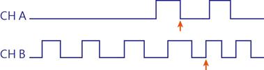
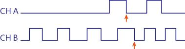
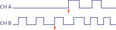
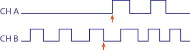
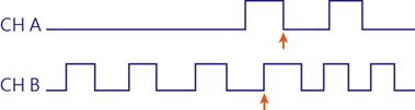
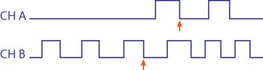
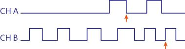
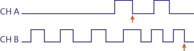
CHA_RISE_TO_CHB_RISE: First CH A rising edge to first CH B rising edge
CHA_RISE_TO_CHB_FALL: First CH A rising edge to first CH B falling edge
CHA_FALL_TO_CHB_RISE: First CH A falling edge to first CH B rising edge
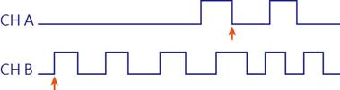
CHA_FALL_TO_CHB_FALL: First CH A falling edge to first CH B falling edge
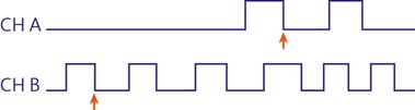
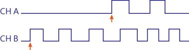
CHA_RISE_TO_NEXT_CHB_RISE: Next CH B rising edge comes after first CH A rising edge
CHA_RISE_TO_NEXT_CHB_FALL: Next CH B falling edge comes after first CH A rising edge
CHA_FALL_TO_NEXT_CHB_RISE: Next CH B rising edge comes after first CH A falling edge
CHA_FALL_TO_NEXT_CHB_FALL: Next CH B falling edge comes after first CH A falling edge
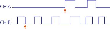
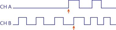
CHA_RISE_TO_PREV_CHB_RISE: First CH A rising edge to previous CH B rising edge
CHA_RISE_TO_PREV_CHB_FALL: First CH A rising edge to previous CH B falling edge
CHA_FALL_TO_PREV_CHB_RISE: First CH A falling edge to previous CH B rising edge
CHA_FALL_TO_PREV_CHB_FALL: First CH A falling edge to previous CH B falling edge
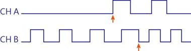
CHA_RISE_TO_FAREST_CHB_RISE
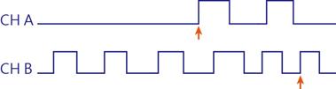
CHA_RISE_TO_FAREST_CHB_FALL
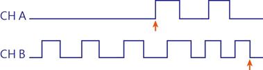
CHA_FALL_TO_FAREST_CHB_RISE
CHA_FALL_TO_FAREST_CHB_FALL
CHA_HIGH_TIMECHA_LOW_TIMECHA_HIGH_PULSE_COUNTCHA_LOW_PULSE_COUNTCHA_RISE_EDGE_COUNTCHA_FALL_EDGE_COUNTCHA_EDGE_COUNT
The following measurements are only available for Mixed-Signal Oscilloscope series.
CHA_SLEW_RATECHA_V_MAXCHA_V_MINCHA_V_PPCHA_V_HIGHCHA_V_LOWCHA_V_AMPLITUDECHA_V_MEANCHA_RISE_TIMECHA_FALL_TIME
-
Minimum limit:
For time measurements, units: ns, us, ms, s
For voltage measurements, units: mV, V
For slew rate measurements, units: mV/us, mV/ms, V/us, V/ms
Xstands for no limitation. -
Maximum limit:
For time measurements, units: ns, us, ms, s
For voltage measurements, units: mV, V
For slew rate measurements, units: mV/us, mV/ms, V/us, V/ms
Xstands for no limitation. -
(optional) CH A reference voltage
For analog channels, units: mV, V
Example: 90% means 90% of the reference channel voltage.
Example: 1.5V for directly set the reference voltage.
-
(optional) CH B reference voltage
For analog channels, units: mV, V
Example: 90% means 90% of the reference channel voltage.
Example: 1.5V for directly set the reference voltage.
-
(optional) CH A pass count
Ignore N times of the condition is met.
-
(optional) CH B pass count
Ignore N times of the condition is met.
Example:
1 2 3 4 5 | |
Analog channel example (Mixed-Signal Oscilloscope series ONLY)
1 2 3 4 5 6 7 8 | |
HWStrap
A single line input that defines the hardware strap conditions. Columns are defined as follows:
- Target Channel:
CH0(for digital channel 0), only for display purpose. - Target Channel Label: Reference to label defined in
Channel - Reference Channel Label: Reference to label defined in
Channel -
Reference Channel Type:
Reference Channel Type CHANNEL_RISINGCHANNEL_FALLINGCHANNEL_CHANGING -
Specification Value: Enter 0 or 1 for expected value, failed on result is not as expected.
-
CH A Ref. Voltage: For analog channels
Units can be in voltages (mV, V) or percentages (%).
Example: 90% means 90% of the reference channel voltage.
Example: 1.5V for directly set the reference voltage.
-
CH B Ref. Voltage: For analog channels
Units can be in voltages (mV, V) or percentages (%).
Example: 90% means 90% of the reference channel voltage.
Example: 1.5V for directly set the reference voltage.
-
CH A Pass Counts:
Ignore N times of the condition is met.
-
CH B Pass Counts: Enter 0 or 1 for expected value.
Ignore N times of the condition is met.
Example:
1 2 3 4 5 | |
Analog channel example (Mixed-Signal Oscilloscope series ONLY)
[HwStrap] //Analog Channel (MSO series ONLY)
CH(A)1, VCC (1.8V), VDD (1.5V), CHANNEL_RISING, 1, 90%, 90%, 0, 0
;