Add internal node
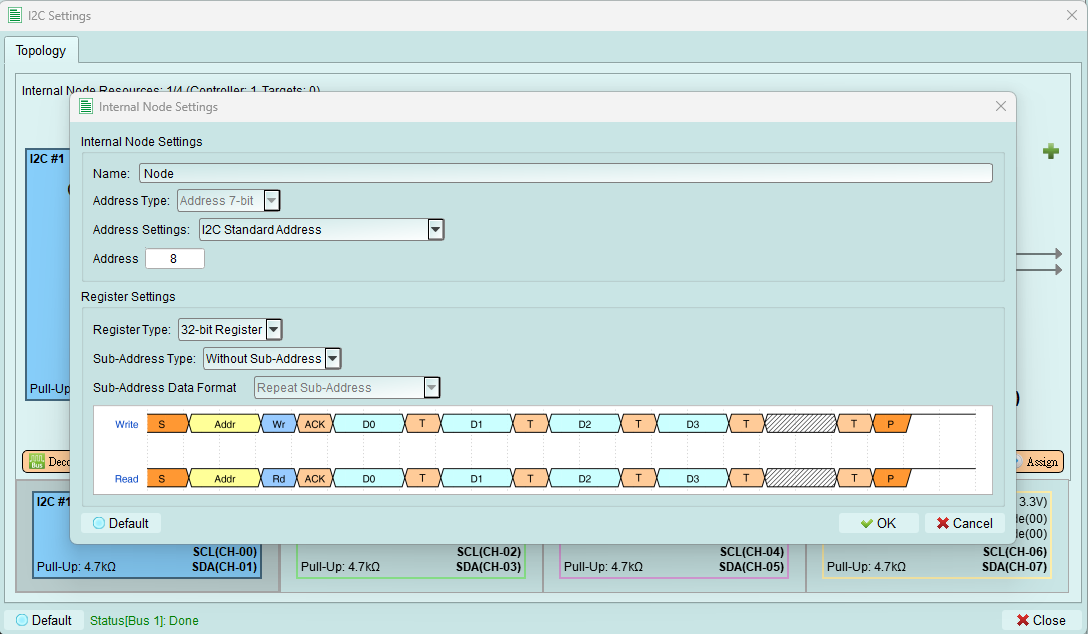
Create virtual I2C target devices to simulate multi-device scenarios.
Overview
Internal nodes are virtual I2C devices that respond to bus transactions. They allow you to test controller behavior without connecting physical devices.
After configuration: Press the Assign button to activate the internal node on the bus.
Configuration options
1. Name
Set a descriptive name for this internal node for easy identification.
Examples:
- "EEPROM_1"
- "Temperature_Sensor"
- "RTC"
- "Test_Device_0x50"
2. Address type
Select the addressing mode for this node.
Current support: 7-bit addressing mode only
Future versions may support:
- 10-bit addressing
- Additional I2C extensions
3. Address settings
Choose the addressing range for this internal node:
I2C standard address
Restricts address to the standard I2C device range: 0x08 to 0x77
Use this mode to:
- Follow I2C specification
- Avoid reserved addresses
- Ensure compatibility with all controllers
I2C address (include reserved address)
Allows the full address range: 0x00 to 0x7F
Reserved addresses to note:
- 0x00: General call address
- 0x01-0x07: CBUS, different bus format, reserved
- 0x78-0x7F: 10-bit addressing, reserved
Use this mode to:
- Test reserved address handling
- Use general call functionality
- Advanced protocol testing
4. Address value
Enter the specific I2C address for this internal node.
Guidelines:
- Must be unique among all nodes on the bus
- Must fall within the selected address range
- Avoid conflicts with external devices
Register settings
Configure the internal node's register behavior.
1. Register type
Set the register depth for the internal node.
Current support: 32-bit register only
What this means: The internal node simulates a device with 32-bit register storage.
2. Sub-address type
Configure whether the internal node uses sub-addressing (register addressing).
Without sub-address
Internal node does not use sub-addressing.
Behavior:
- Simpler protocol
- Direct data READ/WRITE without register selection
- Suitable for simple I2C devices
8-bit sub-address
Internal node uses 8-bit sub-addressing for register access.
Current support: 8-bit sub-address only
Behavior:
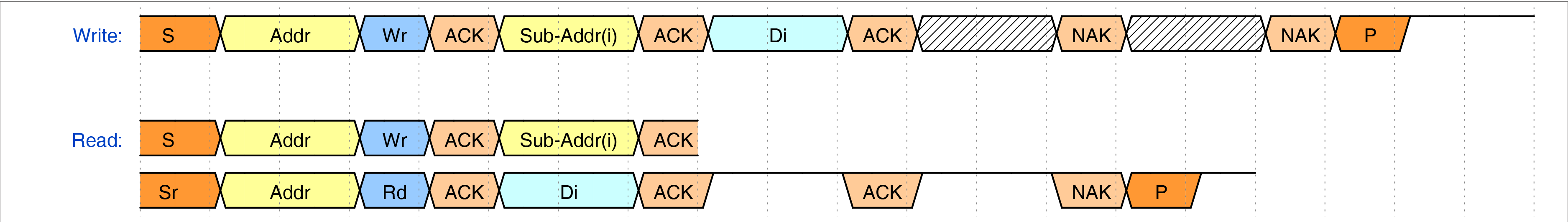
- First byte after address is the sub-address (register address)
- Subsequent bytes are data for that register
- Matches common EEPROM and sensor behavior
3. Sub-address data format
Configure how the internal node handles sub-addresses during multi-byte transactions.
Availability: Only when 8-bit Sub-Address is selected
Repeat sub-address
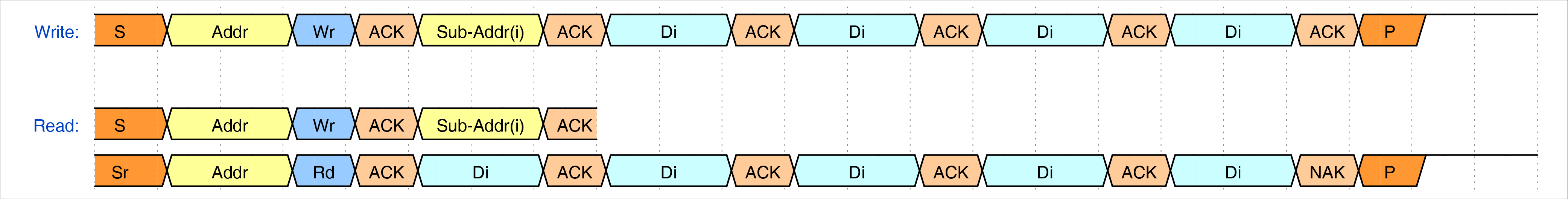
Sub-address remains the same for all bytes in the transaction.
Use case: Reading or writing multiple bytes to/from the same register
Example: Write 4 bytes to register 0x10 - Byte 1 → Register 0x10 - Byte 2 → Register 0x10 - Byte 3 → Register 0x10 - Byte 4 → Register 0x10
Increment sub-address
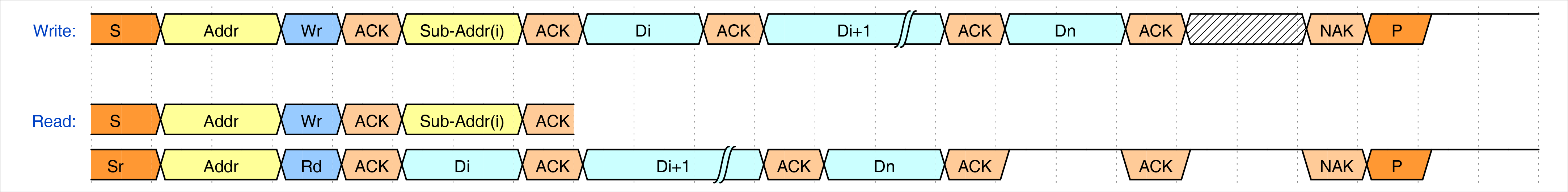
Sub-address increments by 1 for each byte in the transaction.
Use case: Sequential register access (common in EEPROMs)
Example: Write 4 bytes starting at register 0x10 - Byte 1 → Register 0x10 - Byte 2 → Register 0x11 - Byte 3 → Register 0x12 - Byte 4 → Register 0x13
Increment loop sub-address
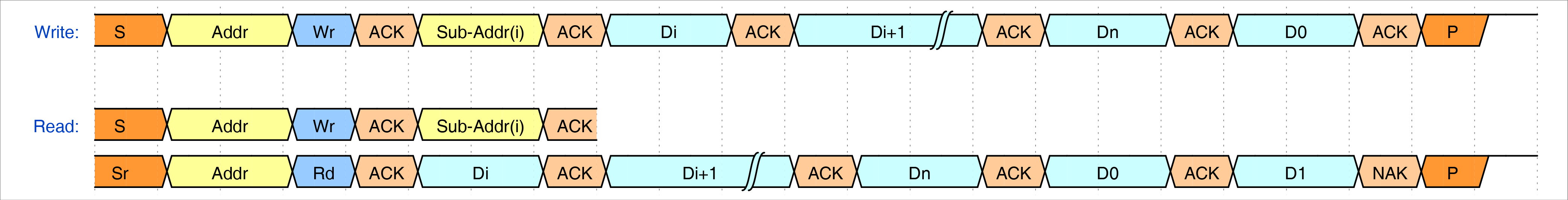
Sub-address increments and wraps around at register boundary.
Use case: Circular buffer access or page-based EEPROMs
Example: Write 4 bytes starting at register 0xFE (assuming 8-bit register space) - Byte 1 → Register 0xFE - Byte 2 → Register 0xFF - Byte 3 → Register 0x00 (wraps around) - Byte 4 → Register 0x01
Ignore sub-address
Sub-address byte is acknowledged but ignored. All data goes to the same location.
Use case: Testing controller behavior when target doesn't implement sub-addressing properly
Tips and best practices
Choosing address format
- Use Standard address range for normal testing
- Use Include reserved range only when testing edge cases or protocol extensions
Sub-addressing
- Increment mode is most common (EEPROMs, flash)
- Repeat mode for FIFO-like devices
- Loop mode for circular buffers
- Ignore mode for troubleshooting and edge testing
Multiple internal nodes
Create multiple internal nodes to:
- Simulate complete systems
- Test controller multi-device handling
- Verify address arbitration
- Check for address conflicts
Remember: Total controllers + internal nodes must not exceed 4