Internal node
Create virtual I3C and legacy I2C target devices for comprehensive bus testing.
I3C node configuration
Configure virtual I3C target devices with complete device characteristics.
1. Name
Set a descriptive name for this internal node for easy identification.
Examples:
- "Sensor_1"
- "EEPROM_0x50"
- "Test_Target_A"
2. Static address
Set the static I3C address (if the device supports static addressing).
Range: 0x08 to 0x7D (I3C allows limited static addresses)
Note: Many I3C devices use dynamic addressing only. Leave blank if not using static address.
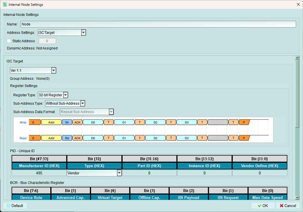
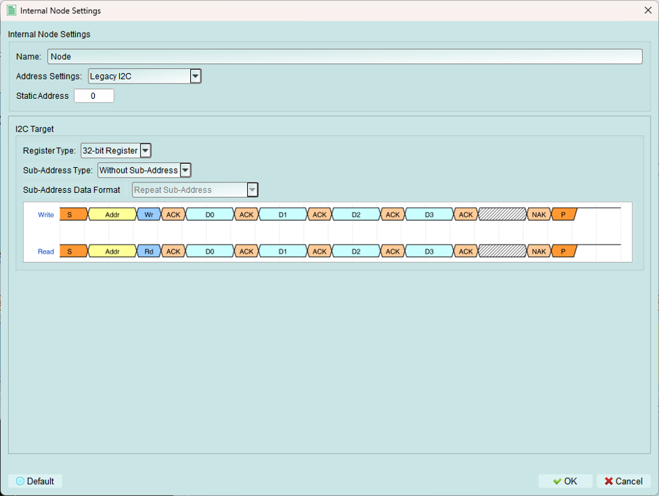
3. Register settings
Configure how the internal node's registers behave.
Register type
Current support: 32-bit register only
The internal node simulates a device with 32-bit register storage.
Sub-address type
Choose whether the node uses register addressing:
Without sub-address

No sub-addressing (register addressing) is used.
Behavior: Direct data READ/WRITE without register selection.
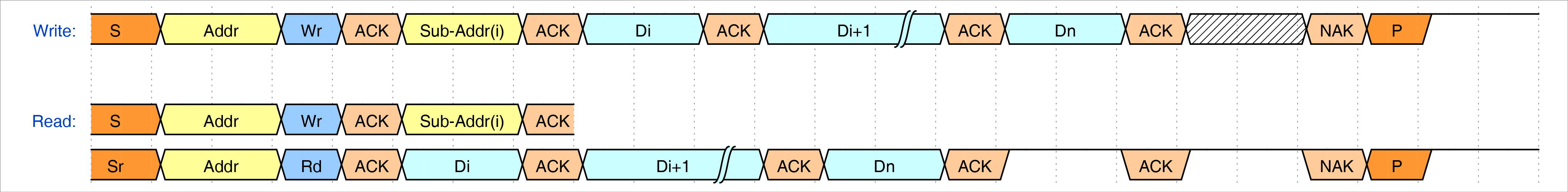
8-bit sub-address
Uses 8-bit sub-addressing for register access.
Current support: 8-bit sub-address only
Behavior: First byte after address selects the register, subsequent bytes are data.
Sub-address data format
Configure multi-byte transaction behavior. Available only when 8-bit Sub-Address is selected.
Repeat sub-address
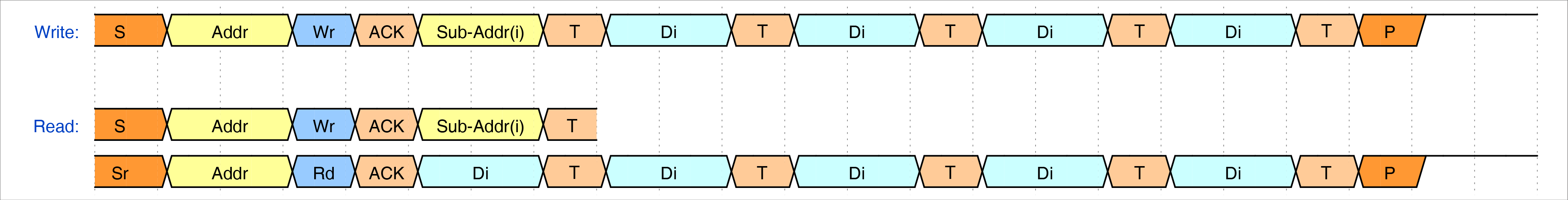
All bytes in the transaction access the same register.
Example: Write 4 bytes to register 0x10 - All 4 bytes → Register 0x10
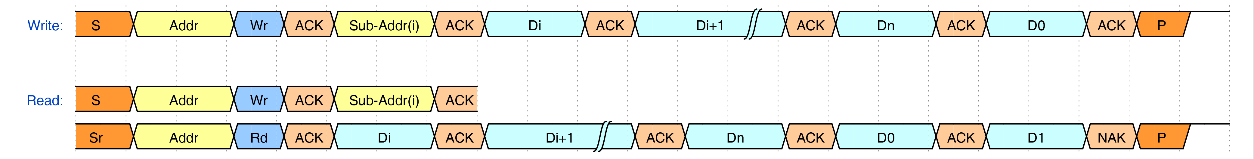
Increment sub-address

Sub-address increments by 1 for each byte.
Example: Write 4 bytes starting at register 0x10 - Byte 1 → 0x10, Byte 2 → 0x11, Byte 3 → 0x12, Byte 4 → 0x13
Increment loop sub-address
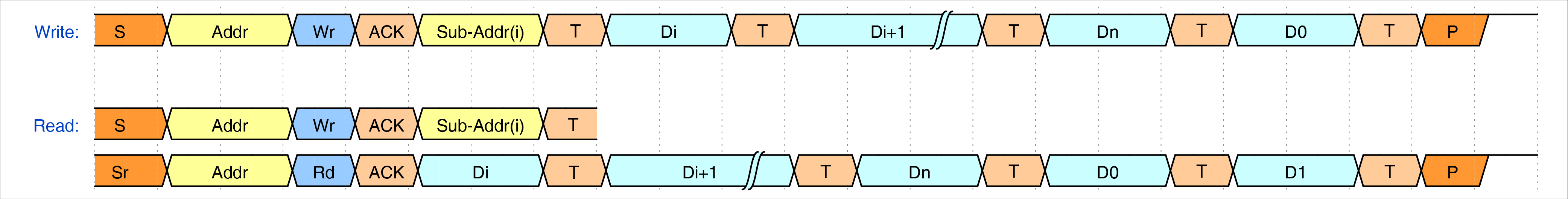
Sub-address increments and wraps at register boundary.
Example: Write 4 bytes starting at 0xFE - Byte 1 → 0xFE, Byte 2 → 0xFF, Byte 3 → 0x00, Byte 4 → 0x01
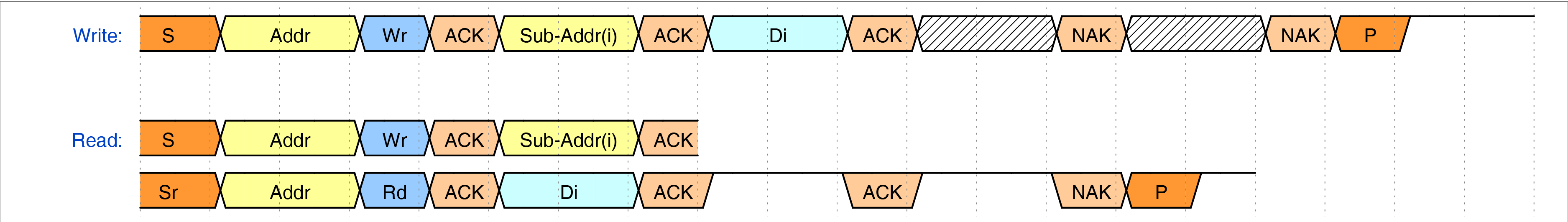
Ignore sub-address

Sub-address byte is acknowledged but ignored.
Use for: Testing edge cases or non-compliant behavior.
4. I3C node information
Configure I3C-specific device characteristics.
PID (Provisional ID)
Build the 48-bit unique device identifier.
Components:
- Manufacturer ID
- Part ID
- Instance ID
Source: Obtain from device datasheet or MIPI I3C specification.
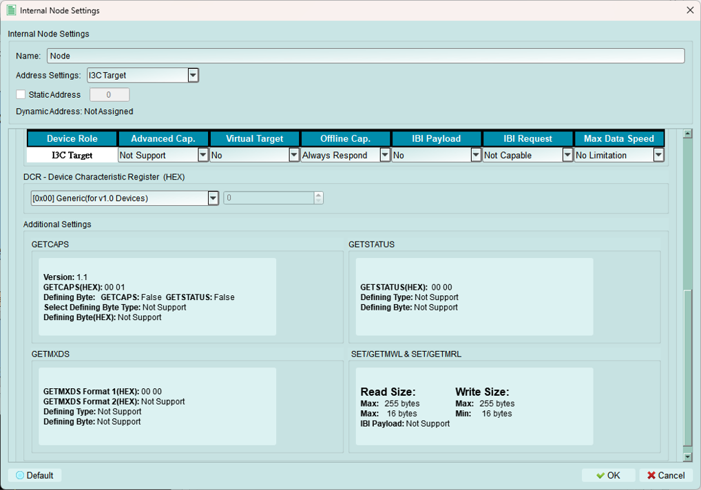
BCR (Bus Characteristics Register)
Configure the Bus Characteristics Register.
Important: BCR settings affect available options in other settings.
Defines:
- Device role (I3C vs. I2C)
- Advanced capabilities
- IBI support
- Offline capability
- Maximum data speed
DCR (Device Characteristics Register)
Set the Device Characteristics Register value.
Options:
- Predefined classes: Select from standard device types
- Custom: Type a specific value in the spinbox
Defines: Device class (sensor, memory, etc.)
Additional settings
1. GETCAPS (Get Capabilities)
Configure how the internal node responds to GETCAPS CCC.
Version 1.0:
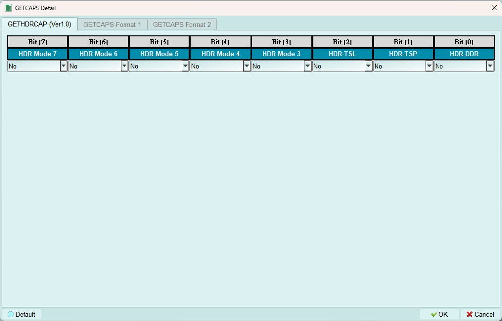
Available when I3C specification version 1.0 is selected.
Format 1 (Simple):
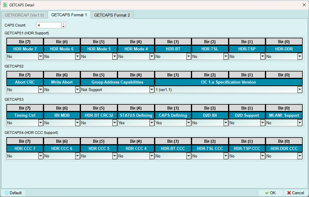
Basic capabilities response.
Enable Format 2:
- Set CAPS Defining bit to enable GETCAPS Format 2
- Set STATUS Defining bit to enable GETSTATUS Format 2
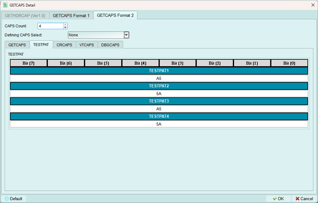
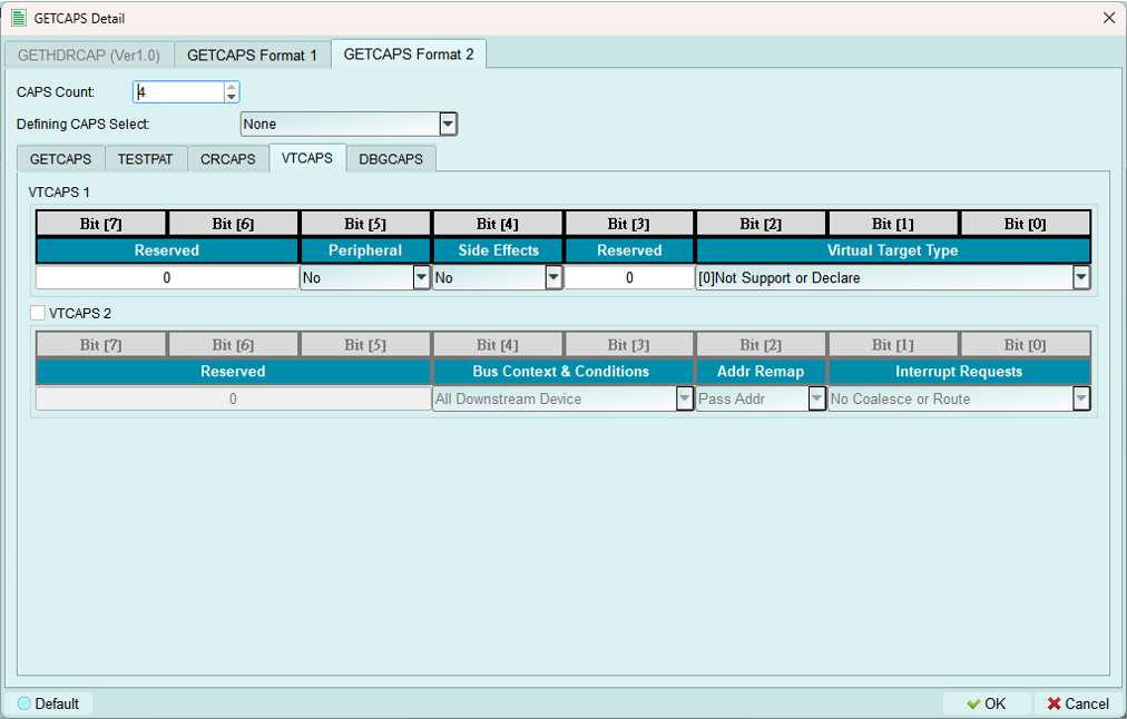
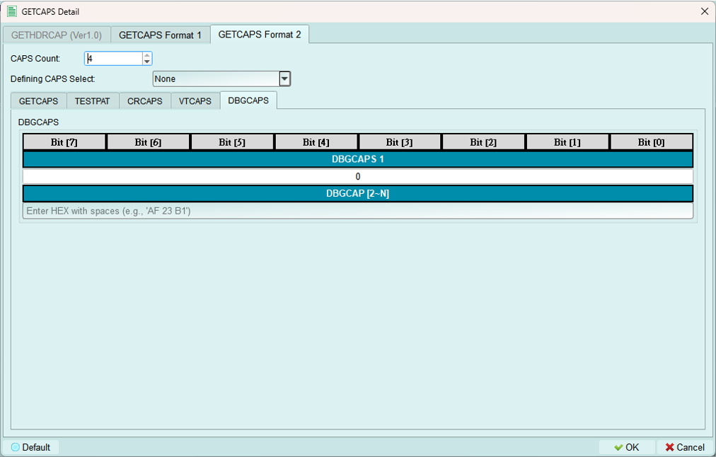
Format 2 (Defining Byte):
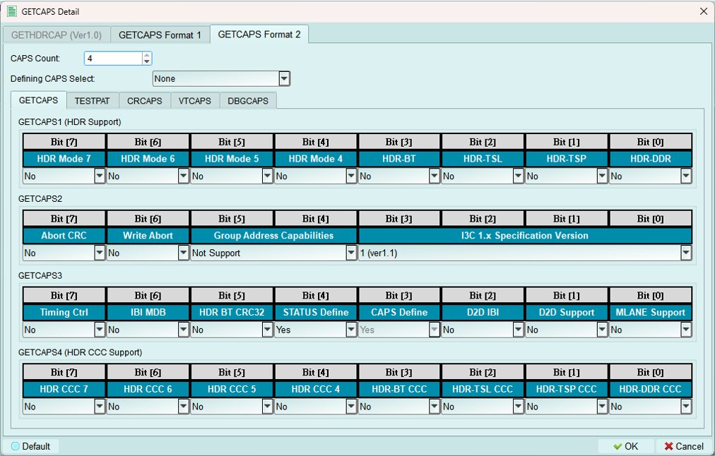
Currently supports one type of defining byte per configuration.
Includes base GETCAPS Format 1 fields plus additional capability bytes:
TESTPAT (Test Pattern):
CRCAPS (Clock Rate Capabilities):
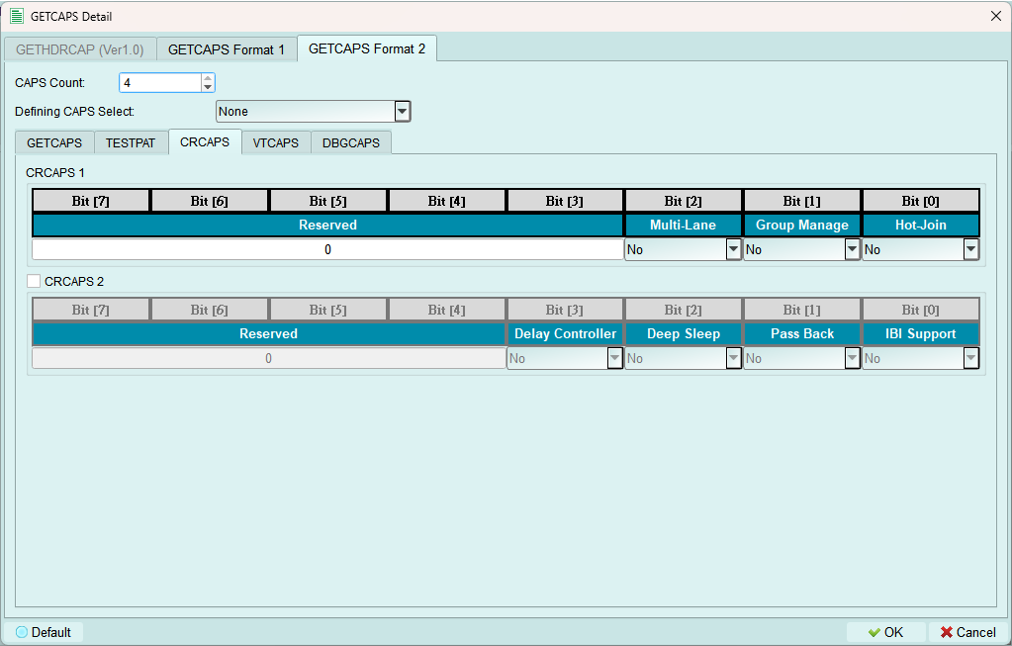
VTCAPS (Virtual Target Capabilities):
DBGCAPS (Debug Capabilities):
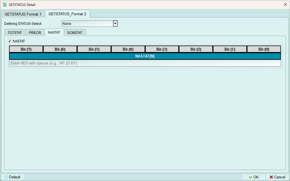
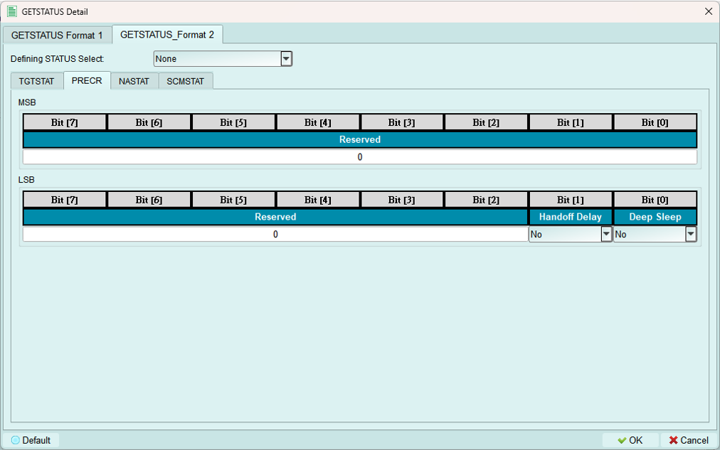
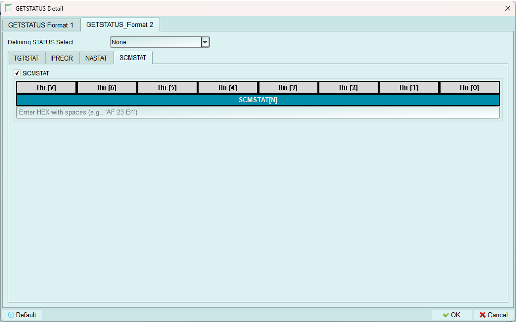
2. GETSTATUS (Get Status)
Configure how the internal node responds to GETSTATUS CCC.
Format 1 (Simple):
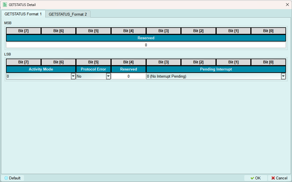
Basic status response with standard status fields.
Format 2 (Defining Byte):
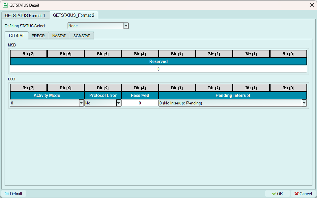
Currently supports one type of defining byte per configuration.
Includes base GETSTATUS Format 1 fields plus additional status bytes:
NASTAT (Not Acknowledged Status):
PRECR (Pending Read Error Count Report):
SCMSTAT (Secondary Controller Mode Status):
3. GETMXDS (Get Max Data Speed)
Configure maximum data speed capabilities response.
Format 1 & 2 (Simple):
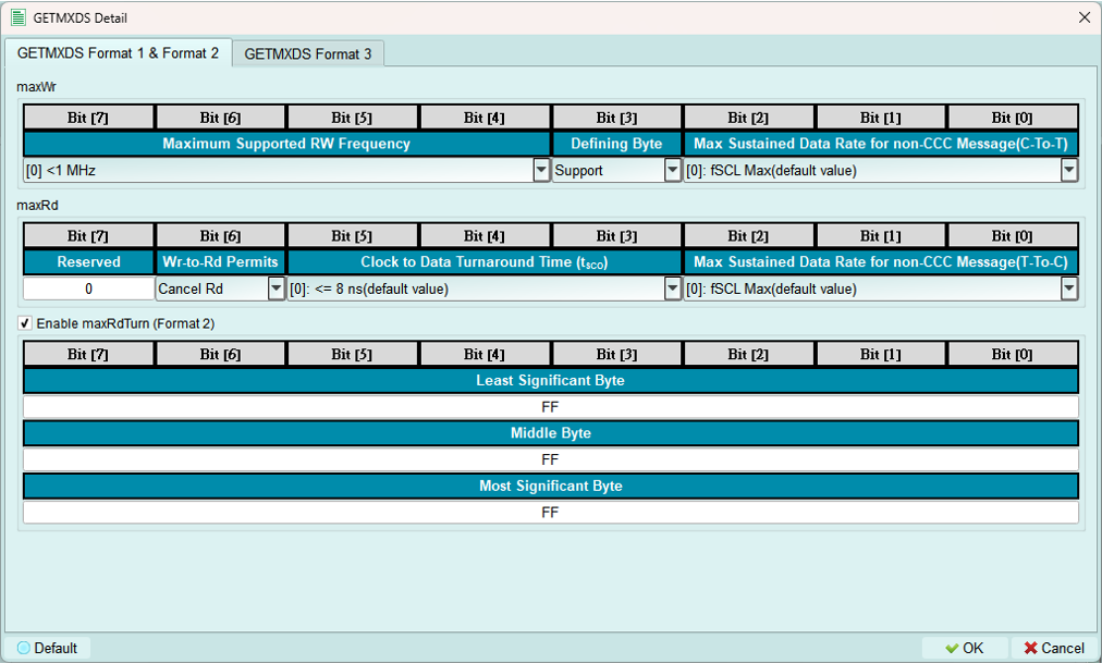
Basic max data speed response.
Enable Format 3:
Select Support in the Defining Byte field to enable defining byte format (Format 3).
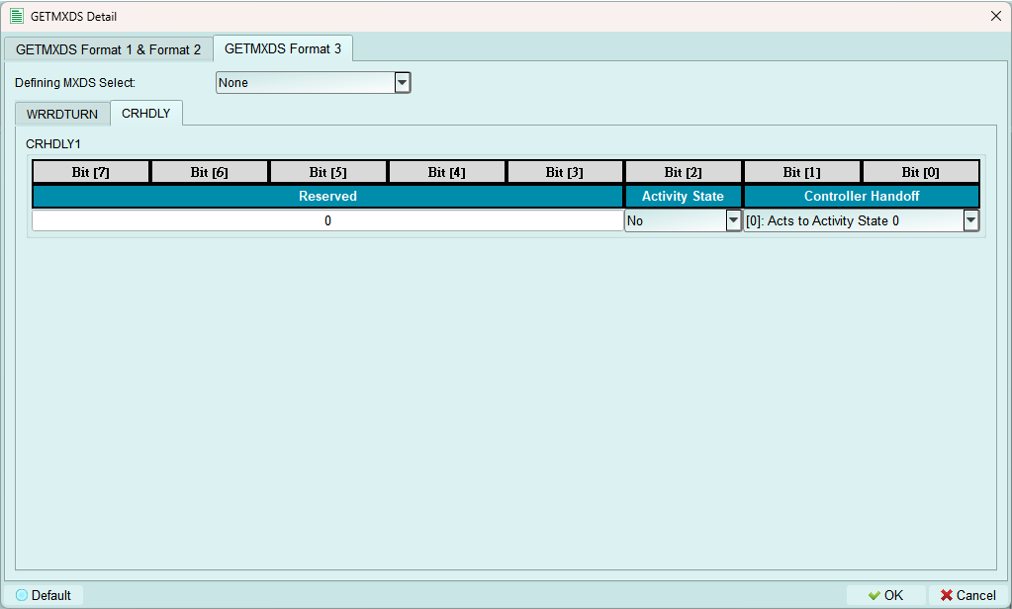
Format 3 (Defining Byte):
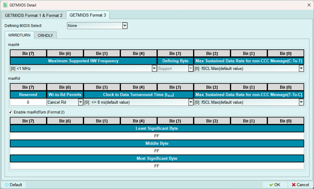
Currently supports one type of defining byte per configuration.
Includes base GETMXDS fields plus:
WRRDTURN (Write-Read Turnaround): Shown above
CRHDLY (Clock-to-Data Turnaround Delay):
4. MWL & MRL (Max Write/Read Length)
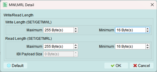
Configure maximum write length (MWL) and maximum read length (MRL) for the device.
IBI Size: Only available when BCR IBI-related bits are set to Support.
Purpose:
- Define buffer size limits
- Prevent overflow conditions
- Match actual device capabilities
Legacy I2C node configuration
Create virtual legacy I2C devices that operate on the I3C bus.
Use cases:
- Test mixed I3C and I2C bus scenarios
- Simulate legacy device compatibility
- Verify backward compatibility behavior
1. Name
Set a descriptive name for identification.
2. Static address
Set the I2C address for this legacy device.
Range: 0x08 to 0x77 (standard I2C device range)
Note: I2C devices always use static addresses, not dynamic assignment.
3. Register settings
Configure register behavior for the legacy I2C node.
Register type
Current support: 32-bit register only
Sub-address type
Without sub-address

No register addressing is used.
8-bit sub-address
Uses 8-bit sub-addressing for register access.
Current support: 8-bit sub-address only
Sub-address data format
Available only when 8-bit Sub-Address is selected.
Repeat sub-address

All bytes access the same register.
Increment sub-address
Sub-address increments for each byte (common for EEPROMs).
Increment loop sub-address
Sub-address increments with wraparound.
Ignore sub-address
Sub-address is acknowledged but not used.
I3C stress test
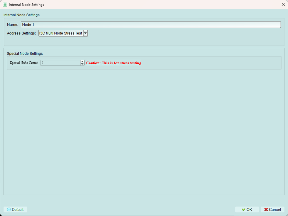
Test controller IBI handling under stress conditions.
Function: Continuously sends IBI (In-Band Interrupt) packets from the internal node.
Purpose: Test the controller's ability to handle a high volume of IBI requests.
Use cases:
- Stress testing controller IBI handling
- Verifying IBI queue management
- Testing IBI priority mechanisms
- Validating controller performance under load
Tips and best practices
I3C vs. I2C nodes
Use I3C nodes when:
- Testing I3C-specific features (DAA, IBI, HDR)
- Simulating modern I3C devices
- Need dynamic addressing
Use I2C legacy nodes when:
- Testing backward compatibility
- Simulating legacy devices on I3C bus
- Verifying mixed-mode operation
Device characteristics
- Use realistic PID values from actual devices or create unique test values
- BCR should accurately reflect device capabilities
- DCR should match the type of device you're simulating
- Configure GETCAPS, GETSTATUS, GETMXDS to match real device behavior
Sub-addressing
- Increment mode: Most common (EEPROMs, registers)
- Repeat mode: FIFO-like devices
- Loop mode: Circular buffers
- Ignore mode: Edge case testing
Stress testing
- Use IBI stress test to validate controller robustness
- Start with slow IBI rate, increase to find limits
- Monitor bus performance under stress
- Verify no lost IBI packets