Controller mode
Configure I2C controller settings, timing parameters, and send transactions to target devices.
Timing settings
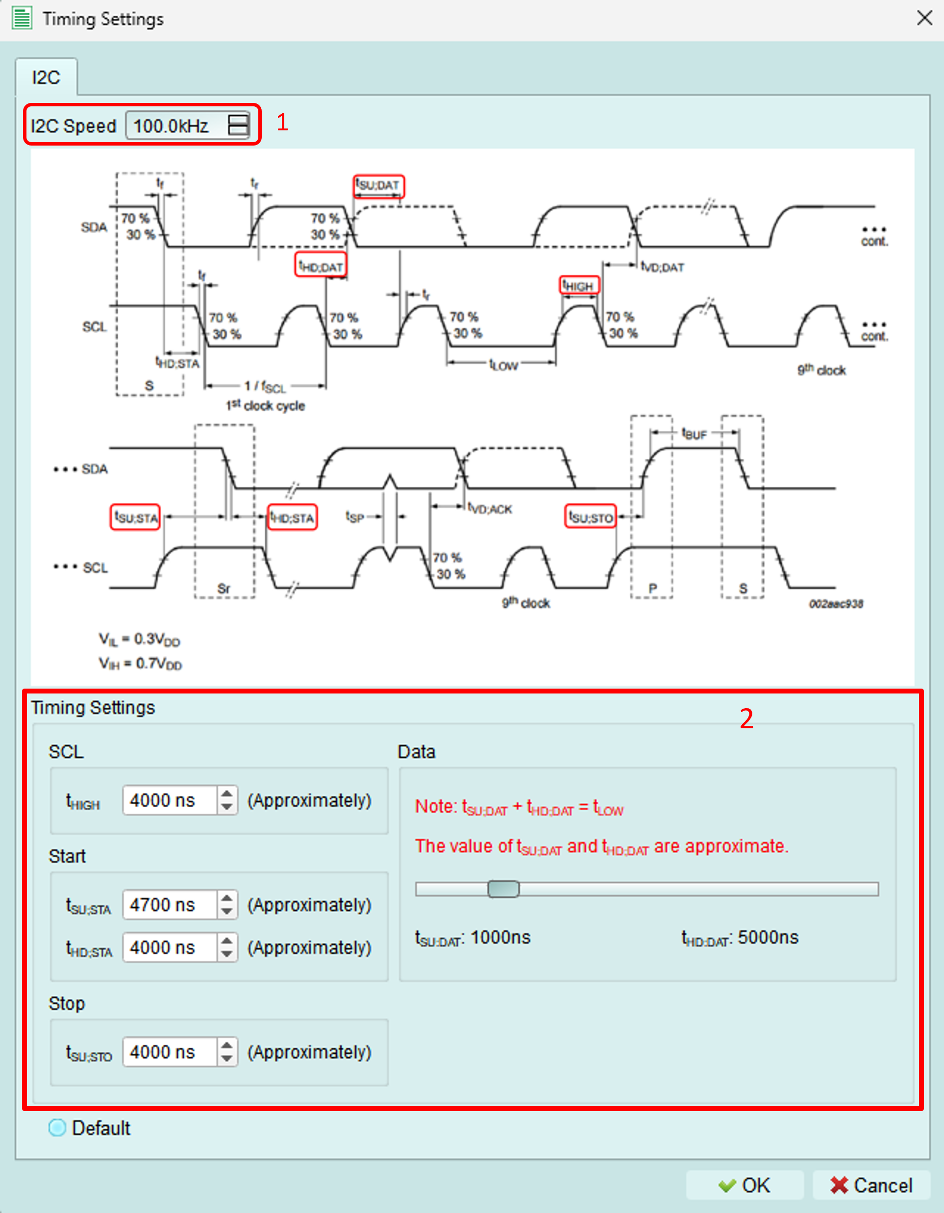
Adjust I2C timing parameters to match your device requirements or test edge cases.
1. Clock frequency
Set the I2C clock (SCL) frequency.
Range: 1 kHz to 1000 kHz (1 MHz)
Standard I2C speeds:
- Standard mode: 100 kHz
- Fast mode: 400 kHz
- Fast-mode Plus: 1000 kHz (1 MHz)
2. Timing components
Adjust individual timing components for precise control.
Adjustable range: 5 ns to 20 μs per component
Components:
- Setup time (SDA before SCL)
- Hold time (SDA after SCL)
- Clock high time
- Clock low time
- START/STOP conditions timing
Interactive adjustment:
Drag the slider bar to adjust the setup and hold time of data signals dynamically.
Functions
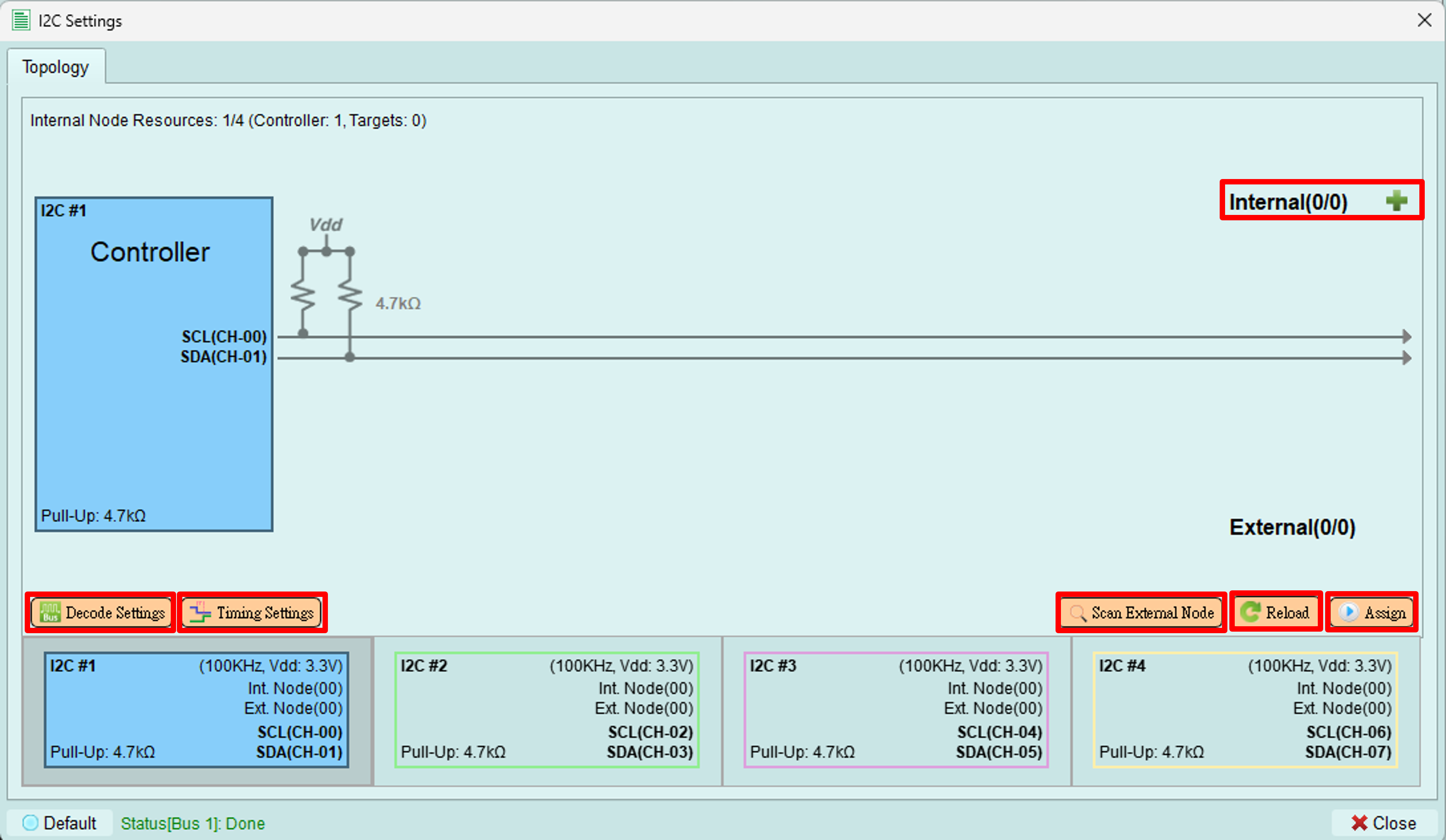
Assign
Upload the configured topology to the exerciser device.
What's uploaded:
- Number of controllers
- Internal node configurations
- Device addresses
- Internal node types and register settings
Purpose: The device needs this information to properly send commands and respond to bus transactions.
When to use: After making any changes to:
- Internal nodes
- Addresses
- Mode settings
- Bus configuration
Reload
Reload the topology from the exerciser device and display it in the software.
Use cases:
- Verify what's currently loaded on the device
- Synchronize after external changes
- Refresh after programmatic configuration (e.g., via Python API)
Scan external node
Scan all available addresses from 0x08 to 0x77 to detect connected devices.
How it works:
- Controller sends transactions to each address
- If a device responds with ACK, it appears in the topology
- Non-responsive addresses are skipped
Benefits:
- Automatically discover connected devices
- Verify device addresses
- Check for address conflicts
- Confirm device connectivity
Time: Scanning all addresses takes a few seconds.
Decode settings
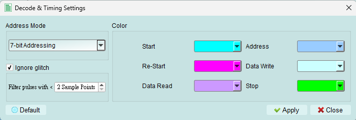
Configure Logic Analyzer parameters for I2C signal decoding.
Settings include:
- SCL (clock) channel assignment
- SDA (data) channel assignment
- Decode display options
- Color coding
Purpose: Proper decode settings ensure the Logic Analyzer correctly interprets I2C signals captured during exerciser operations.
Send packets
To open the wizard, see Wizard in the toolbar.
The I2C wizard provides two methods for sending packets: Quick Send and Packet Constructor.
Quick send
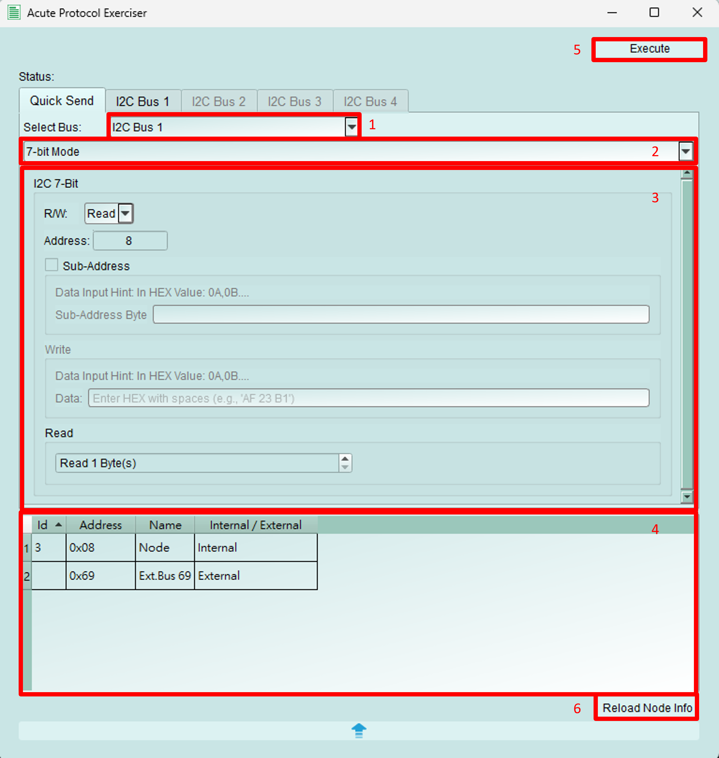
Send simple I2C transactions quickly with a streamlined interface.
Configuration:
- Bus selection: Choose which bus to send the packet from
- Address mode: Select 7-bit, 8-bit, or 10-bit addressing
- This documentation uses 7-bit mode as the example
- Packet details:
- R/W: Select WRITE or READ operation
- Address: Set the target device address
- Sub-address: Set the register address (if sub-addressing is enabled)
- Write data: Enter data bytes to write
- Read byte count: Specify number of bytes to read (for READ operations)
- Address table: Displays information about internal and external nodes
- Send button: Transmit the configured packet
- Reload button: Refresh the address table
Packet constructor
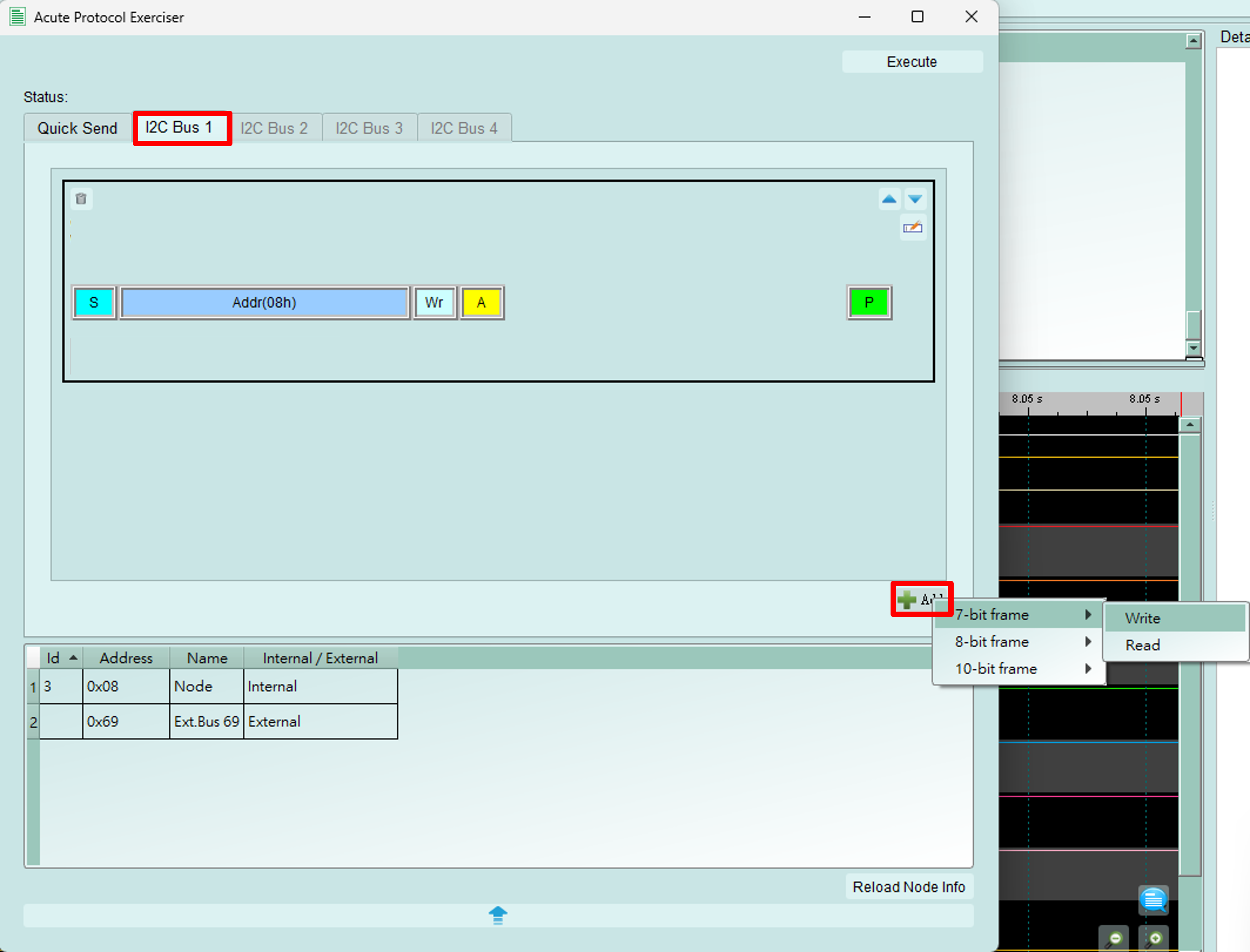
Build complex I2C transaction sequences with multiple packets.
How to use:
- Switch to the Bus tab
- Click the Add button (bottom right)
- Add 7-bit, 8-bit, or 10-bit WRITE or READ packets
- Configure packet details
- Click Execute to send all packets in sequence
This documentation uses 7-bit mode as the example.
Edit packet
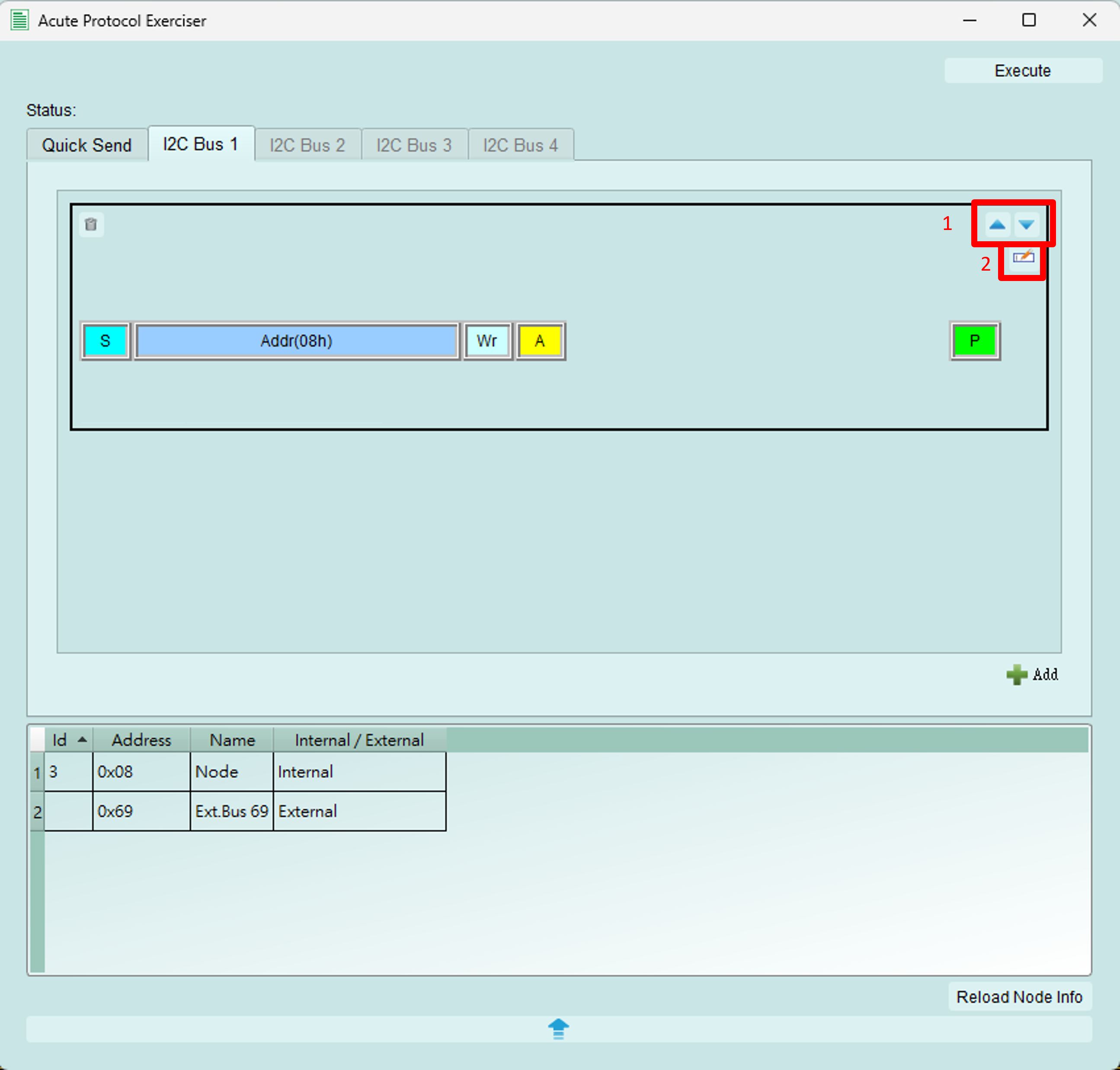
Manage and sequence multiple I2C packets.
Functions:
- Reorder packets: Use arrow buttons to adjust packet execution order
- Edit packet details: Click to open the detailed editing dialog (see below)
- Delete packet: Remove packet from the sequence
- Packet list: View all configured packets
Packet sequence editor
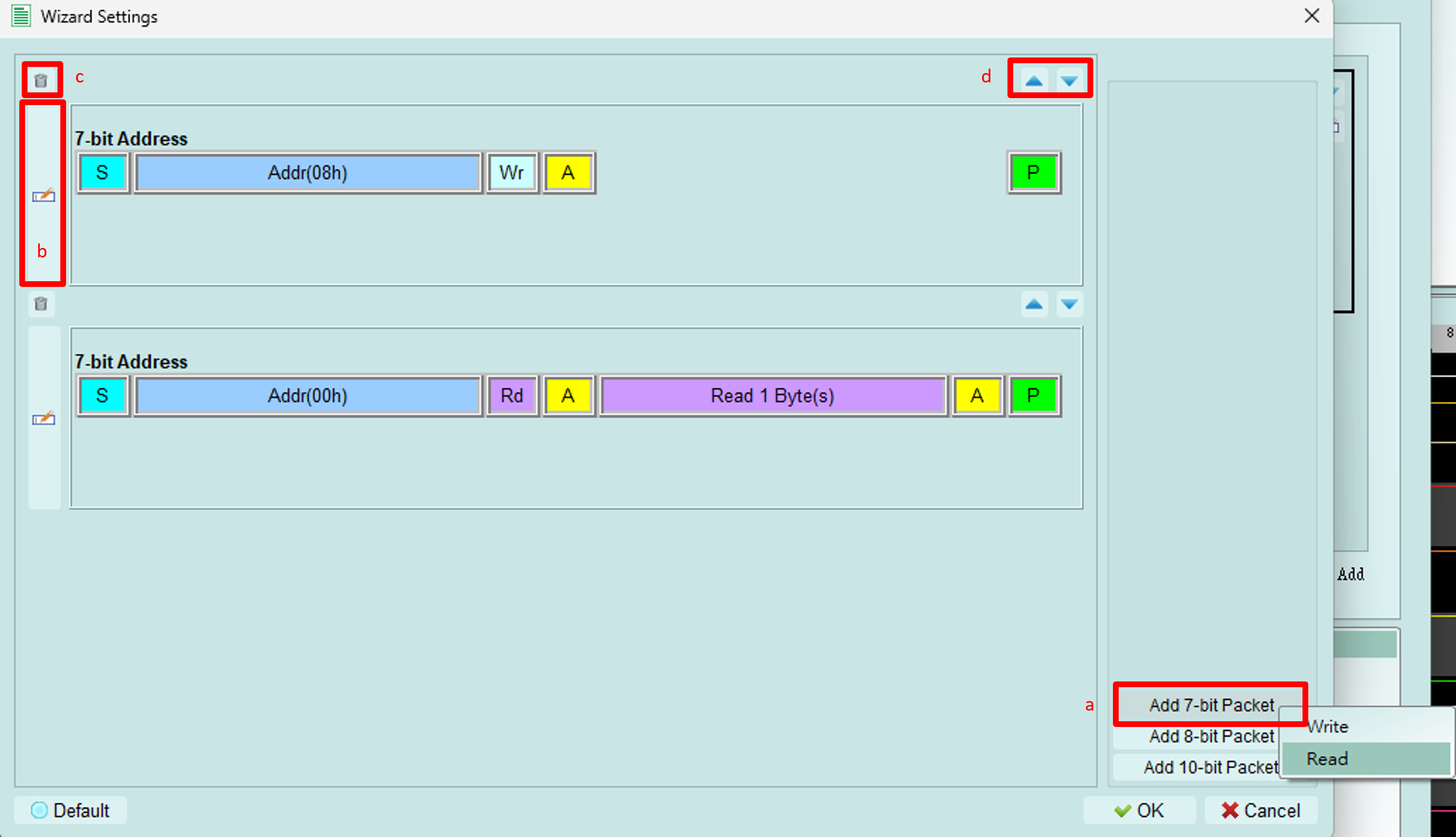
Configure a sequence of WRITE and READ operations.
Operations:
- Add packet: Insert new WRITE or READ packet into the sequence
- Edit packet: Configure packet details (opens detail editor)
- Delete packet: Remove selected packet from sequence
- Reorder: Adjust execution order of packets
Detail packet editor
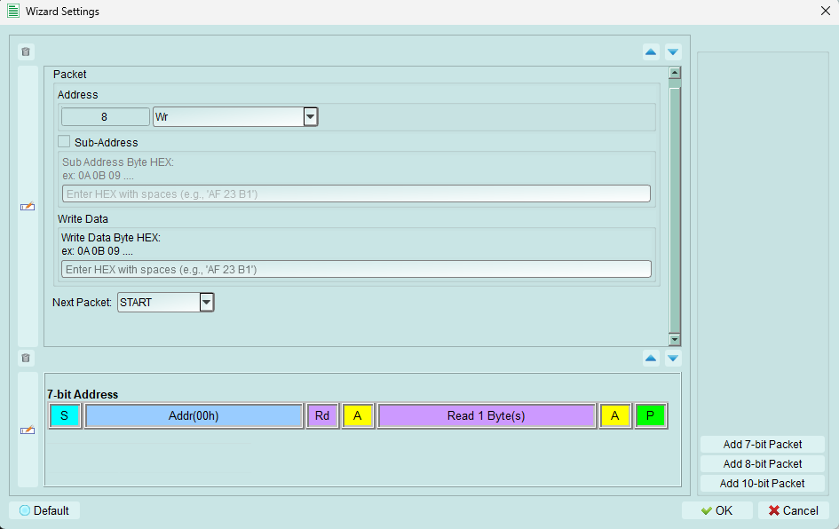
Configure individual packet parameters.
Fields:
- Address: Set device address and choose WRITE or READ operation
- Sub-address: Set register address (if this function is enabled for the target)
- Data:
- WRITE operation: Enter data bytes to transmit
- READ operation: Set the number of bytes to read
- Next packet: Choose the condition between this packet and the next:
- START: New I2C transaction (STOP then START)
- REPEAT START: Continue transaction (no STOP condition)
Tips and best practices
Timing configuration
- Start with standard frequencies (100 kHz or 400 kHz)
- Adjust timing only if testing edge cases or specific requirements
- Verify timing meets I2C specification for your target devices
Quick send vs. Packet constructor
Use Quick Send for:
- Single transactions
- Quick testing
- Simple READ/WRITE operations
Use Packet Constructor for:
- Complex sequences
- Multiple operations
- Testing specific protocol scenarios
- Automated test sequences
Transaction sequences
Common patterns:
EEPROM write: 1. START 2. Address + WRITE 3. Register address 4. Data byte(s) 5. STOP
EEPROM read: 1. START 2. Address + WRITE 3. Register address 4. REPEAT START 5. Address + READ 6. Data byte(s) 7. STOP
Use Repeat Start for read operations to maintain bus control and specify the starting register address.