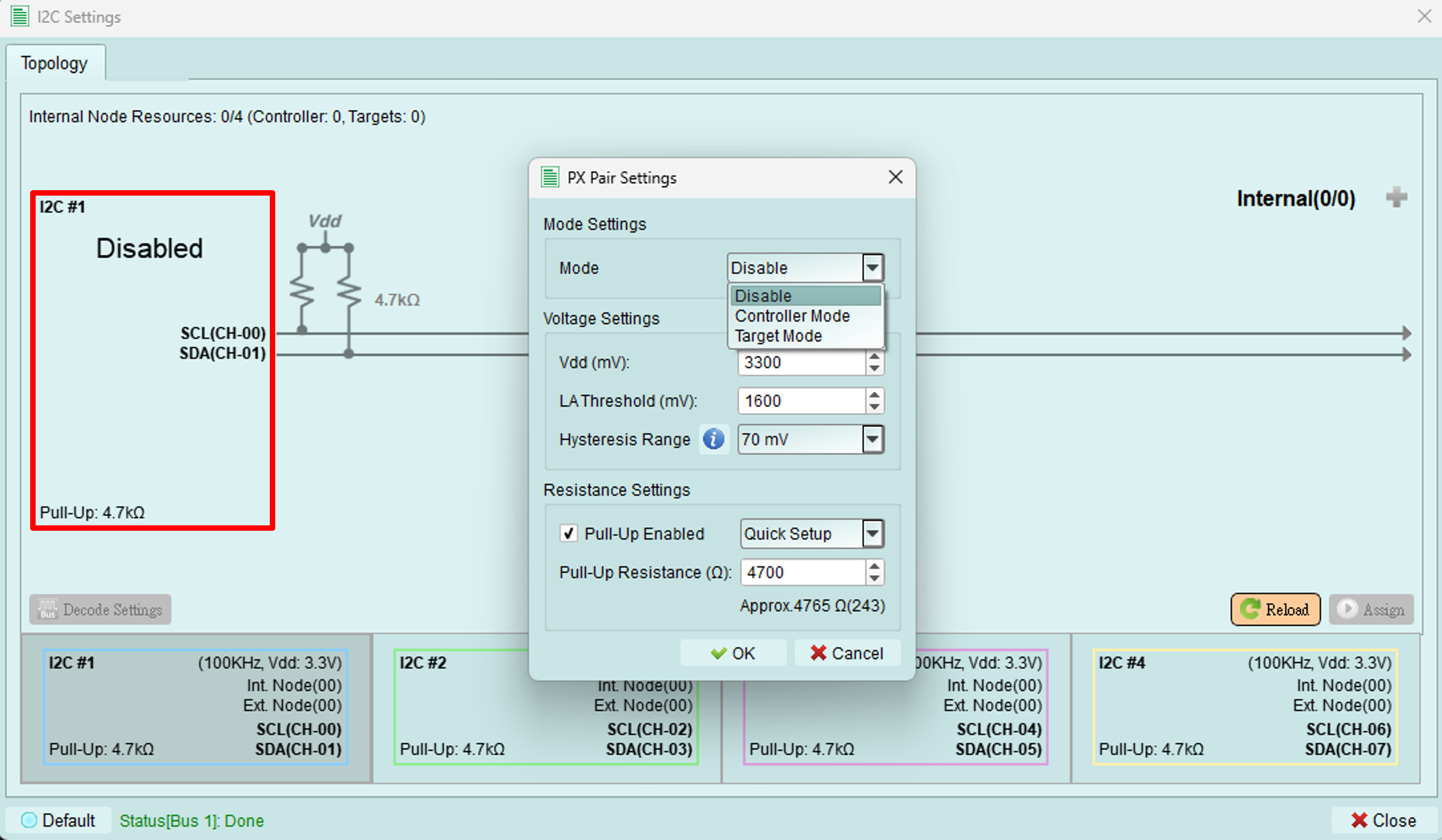
PX pair settings
Configure operating mode, voltage levels, and pull-up resistors for the I2C bus.
Accessing settings
Click the button on the left side of the topology dialog (highlighted in red box) to open the PX Pair Settings dialog.
Mode settings
Choose the operating mode for the exerciser on this bus:
- Controller mode: Exerciser acts as an I2C controller on this bus
- Target mode: Exerciser acts as an I2C target device on this bus
- Disable: Bus is inactive
Internal nodes
In both Controller and Target modes, you can create virtual internal nodes to simulate multiple target devices on the bus.
Limitation: The total number of controllers and internal nodes combined must not exceed 4.
Voltage settings
Configure voltage levels for proper I2C operation and signal decoding.
All voltage values are in millivolts (mV).
1. Vdd
Set the working voltage for the I2C bus.
Typical values:
- 3300 mV (3.3V) - Common for modern devices
- 5000 mV (5.0V) - Legacy and some automotive applications
- 1800 mV (1.8V) - Low-power devices
2. Logic Analyzer threshold
Set the threshold voltage for the Logic Analyzer to properly decode I2C signals.
Recommendation: Set to approximately Vdd/2 for optimal signal detection.
Examples:
- Vdd = 3300 mV → Threshold = 1650 mV
- Vdd = 5000 mV → Threshold = 2500 mV
- Vdd = 1800 mV → Threshold = 900 mV
3. Hysteresis range
Set the hysteresis range for noise immunity.
Purpose: Hysteresis prevents false triggering on noisy signals by requiring different thresholds for low-to-high and high-to-low transitions.
Typical value: 100-300 mV
Resistance settings
Configure pull-up resistors for the I2C bus.
1. Pull-up enabled
Check the checkbox to activate internal pull-up resistors.
When to enable:
- No external pull-up resistors on the bus
- Testing pull-up resistance effects
- Standalone exerciser testing without external components
When to disable:
- External pull-up resistors are present
- Device under test provides pull-ups
- Avoiding conflicts with existing pull-ups
2. Pull-up resistance
Set the pull-up resistance value.
Input methods:
- Type a custom value directly
- Select from common resistance values in the dropdown
Common values:
- 2.2 kΩ - High-speed I2C
- 4.7 kΩ - Fast-mode I2C (typical)
- 10 kΩ - Standard-mode I2C
Selection guidelines:
- Lower resistance: Faster rise times, higher current consumption
- Higher resistance: Slower rise times, lower current consumption
- Match resistance to bus capacitance and speed requirements
Tips and best practices
Voltage configuration
- Always verify Vdd matches your device specification
- Set threshold carefully - incorrect values cause decode errors
- Use a multimeter to measure actual bus voltage if uncertain
Pull-up resistors
- Calculate required resistance based on bus capacitance and speed
- Formula: R = (tr × 0.8473) / (Cb × 0.8473) where tr is rise time, Cb is bus capacitance
- When in doubt, start with 4.7 kΩ for fast-mode I2C
Internal nodes
- Use internal nodes to simulate multi-device scenarios
- Test controller behavior with multiple targets
- Verify proper arbitration and addressing