PX pair settings
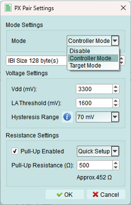
Configure operating mode, voltage levels, and pull-up resistors for the I3C bus.
Accessing settings
Click the large button on the left side of the topology dialog to open the PX Pair Settings dialog.
Mode settings
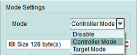
The Acute PX device supports multiple targets and controllers on the same bus. Select the appropriate mode for your testing scenario.
Mode selection options
1. Disable
Deactivate I3C bus functions on this bus.
Use when:
- Bus is not needed for current test
- Preventing accidental bus activity
- Isolating other buses
2. Controller mode
Exerciser simulates an I3C controller with optional target nodes on this bus.
Features:
- Initiate all bus transactions
- Perform dynamic address assignment
- Send CCC commands
- Control bus timing
- Accept in-band interrupts (IBI) from targets
IBI Size configuration:
Define the maximum amount of IBI data the virtual controller will accept from targets.
Use cases:
- Testing target device implementations
- Simulating a controller with multiple targets
- Verifying protocol compliance
3. Target mode
Exerciser simulates I3C target devices on this bus.
Features:
- Respond to controller commands
- Accept dynamic address assignment
- Send IBI requests (if enabled)
- Operate in HDR modes when commanded
Use cases:
- Testing controller implementations
- Simulating sensors or peripherals
- Verifying target behavior
Internal nodes
In both Controller and Target modes, you can create virtual internal nodes to simulate multiple target devices on the bus.
See: Internal Node
Voltage settings
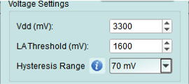
Configure voltage levels for proper I3C operation and signal decoding.
All voltage values are in millivolts (mV).
1. Vdd
Set the working voltage for the I3C bus.
Typical I3C voltages:
- 3300 mV (3.3V) - Most common
- 1800 mV (1.8V) - Low-power I3C
- 1200 mV (1.2V) - Ultra-low-power applications
2. Logic Analyzer threshold
Set the threshold voltage for the Logic Analyzer to properly decode I3C signals.
Recommendation: Set to approximately Vdd/2 for optimal signal detection.
Examples:
- Vdd = 3300 mV → Threshold = 1650 mV
- Vdd = 1800 mV → Threshold = 900 mV
3. Hysteresis range
Set the hysteresis range for noise immunity on I3C signals.
Purpose: Prevents false signal detection on noisy or slow-transitioning signals.
Typical value: 100-300 mV
Resistance settings
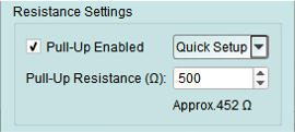
Configure internal pull-up resistors for the I3C bus.
1. Pull-up enabled
Check the checkbox to activate internal pull-up resistors.
When to enable:
- No external pull-up resistors on the bus
- Standalone testing without external hardware
- Testing pull-up effects on signal quality
When to disable:
- External pull-up resistors are present
- Device under test provides pull-ups
- Avoiding conflicts with existing pull-ups
2. Pull-up resistance
Set the pull-up resistance value.
Input methods:
- Type a custom value directly
- Select from common preset values in the dropdown
Common I3C pull-up values:
- 1.0 kΩ - High-speed I3C (push-pull modes)
- 2.0 kΩ - Typical I3C
- 4.7 kΩ - I2C legacy compatibility
Selection guidelines:
- Lower resistance: Faster transitions, higher current
- Higher resistance: Lower power, slower transitions
- I3C typically uses lower resistance than I2C due to push-pull operation
Tips and best practices
Mode selection
Choose Controller mode when:
- Testing target devices
- Need to initiate transactions
- Performing dynamic address assignment
- Sending CCC commands
Choose Target mode when:
- Testing controller implementations
- Simulating sensors or peripherals
- Verifying target response behavior
Voltage configuration
- Always match Vdd to your device specifications
- Verify mixed-voltage devices are compatible
- I3C devices must tolerate the bus voltage
- Legacy I2C devices must operate at the same voltage
Pull-up resistors
- Calculate based on bus capacitance and speed requirements
- I3C uses push-pull for high-speed, open-drain for legacy I2C
- Pull-ups primarily affect open-drain (I2C legacy) operation
- Test with recommended 2.0 kΩ first, adjust as needed