Settings
Protocol Analyzer settings. Review the common rules and product-family UI differences below, then select a protocol from the left menu for parameter details.
Protocol select (common)
After you select a protocol, the settings dialog typically includes:
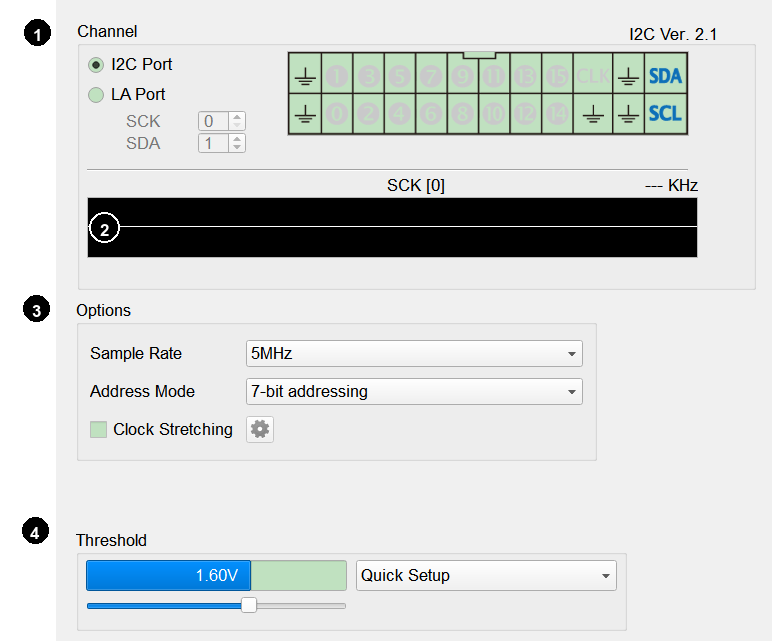
1. Channel: Assign protocol signals to channels or interfaces (UI differs by product family; see below).
2. Waveform preview: The software can automatically detect and show the signal waveform and maximum frequency. The preview bar shows the selected clock channel and the measured bus frequency (KHz). It displays --- KHz when no signal is detected.
3. Options: Protocol packet format or analysis parameters.
4. Trigger Level / Threshold: Set the trigger voltage for the signal level. A common recommendation is about half the DUT operating voltage. Adjust with the slider or by entering a value, or use Quick Setup to apply a preset for common Vcc levels, for example:
- Vcc 5 V → Threshold 2.5 V
- Vcc 3.3 V → Threshold 1.6 V
- Vcc 1.8 V → Threshold 0.9 V
This works the same across product families and is not repeated on each protocol page.
Product-family UI differences
Protocol Analyzer settings differ mainly in the Channel area by product family. The following examples use I2C.
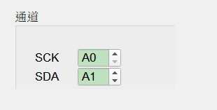
- BusFinder 6000/7000 series, LA3000/LA4000 series
These instruments have Slot A and B (some models also have Slot C and D). Channel numbers are shown as “slot letter + channel index”; for example A0 means channel 0 on Slot A, and B31 means channel 31 on Slot B.
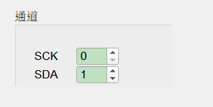
- MSO2000/3000 series, TravelScope 3000 series, TravelLogic 3000/4000 series
Assign signals by logic channel number. For Voltage Detect on supported TravelLogic models, see Voltage Detect at the end of this page.
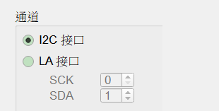
- TravelBus 1000/2000/3000 series
Choose the dedicated I2C interface or the general LA interface. The I2C interface shows the instrument pin map; the LA interface uses general logic channels numbered on the cable.
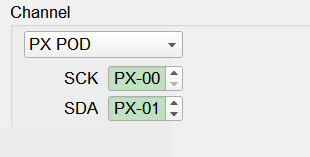
- PX2000 series
First select the device / Pod (for example PX POD), then assign PX channels (for example PX-00, PX-01).
On each protocol page:
- Protocols available on all product lines use a TravelLogic screenshot as the representative UI.
- Protocols limited to a specific line (for example BusFinder only) use that product's screenshot.
- Channel differences, waveform preview, Trigger Level, Voltage Detect, and Voltage Range Settings (voltage-drop trigger) are covered in the common sections above.
- Dialogs used only by SD 3.0 / eMMC (but shared between them)—Vendor CMD, Trigger Settings, Data Trigger, Timeout Trigger—are under Shared SD / eMMC dialogs below and are not repeated on each protocol page.
Voltage Detect
Supported models
Voltage Detect is available only on TravelLogic and LA3000 / LA4000 / BusFinder.
Description
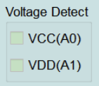
The cable marks these pins with A0 and A1 stickers. Some protocols expose Voltage Detect in Options, with checkboxes such as VCC(A0) and VDD(A1) to enable those pins as voltage-detect channels.
In the Protocol Analyzer report window, the software shows the voltage measured on those pins. The sampling interval is about 1 µs.
Use it to monitor the supply state of an external circuit—for example, when the DUT suddenly loses power, the drop can be detected and shown on screen.
Voltage Range Settings (voltage-drop trigger)
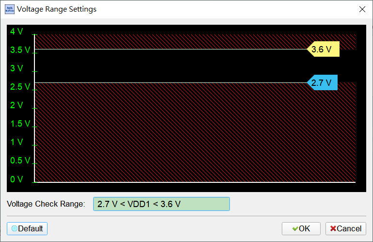
Some protocols offer voltage-drop triggers under Trigger on / Trigger On (for example VCC Drop, VDD Drop, VCC(A0) Drop, VDD1 Drop). Selecting one opens Voltage Range Settings.
Set the voltage check range graphically (e.g. 2.7 V < VDD1 < 3.6 V). Out-of-range zones are shown with red hatching. Use Default to restore the factory range. Default limits may differ by protocol—follow that protocol’s dialog or Default.
Shared SD / eMMC dialogs
The following dialogs appear only for SD 3.0, eMMC, and related timeout settings. The UI and workflow are shared; protocol pages link here instead of repeating the details.
Vendor CMD settings
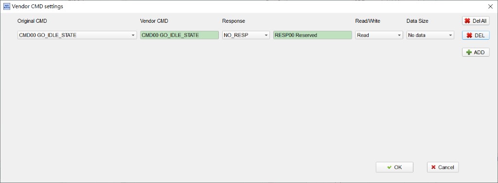
Open from Option → Vendor CMD. Customize Vendor CMD name, Response, Read/Write, and Data Size from Original CMD. Manage the list with ADD / DEL / Del All.
Default is often Original/Vendor CMD00 GO_IDLE_STATE, Response NO_RESP, Read/Write Read, Data Size No data.
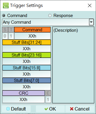
Trigger Settings (Command / Response)
Open from Trigger on when Command/Response (or eMMC CMD / RESP.) is selected. Choose Any Command (or a specific command) and combine S/T/Command/Stuff Bits/CRC/E fields. XXh means don't care. S/T/E are often fixed (S=0, T=1, E=1); Description appears on the right.
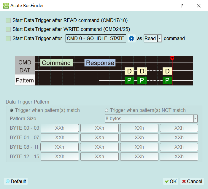
Data Trigger
Open from Trigger on when Data is selected. Optionally start after READ (CMD17/18), WRITE (CMD24/25), or a custom command, then set match / NOT match, Pattern Size, and byte patterns. XXh means don't care for that byte.
Default: start conditions cleared; Trigger when pattern(s) match; Pattern Size often 8 bytes; bytes mostly XXh.
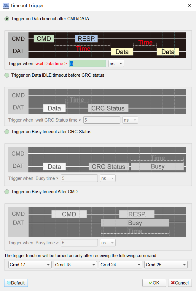
Timeout Trigger
Open from Trigger on → Timeout (mainly eMMC; related SD/MMC timeout settings are the same). Choose Data timeout after CMD/DATA, Data IDLE timeout before CRC status, Busy timeout after CRC Status, or Busy timeout After CMD, and set the time threshold and unit.
Default is often Data timeout after CMD/DATA with > 5 ns; Command filter Default often Cmd 17 / 18 / 24 / 25.