SD 3.0 (SD 3.0)
SD 3.0 Protocol Analyzer settings.
For application notes, probe connection, and measurement details, see Protocol Solution — SD 3.0 / 4.0.
Supported Models
BusFinder
All BF6000/BF7000 models are supported. This feature requires purchasing an additional option.
MSO2000/3000
| MSO2008E | MSO2116E | MSO2116B | MSO2216B | MSO2216B+ | MSO2416B+ |
|---|---|---|---|---|---|
| ● | ● | ● |
| MSO2216M+ | MSO2116E+ | MSO2116B+ |
|---|---|---|
| ● |
Settings
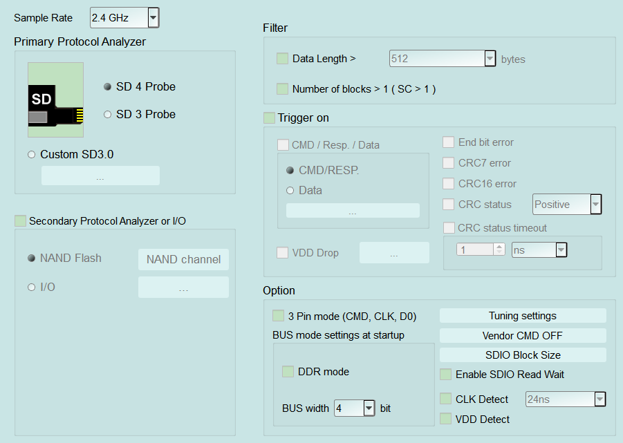
- Settings:
- Sample Rate: Select the sample rate. If Secondary PA (NAND Flash) is enabled, use 1 GHz or below. Default: 2.4 GHz.
- Primary Protocol Analyzer: SD 4 Probe / SD 3 Probe, or Custom SD3.0.
- Secondary Protocol Analyzer or I/O: NAND Flash or I/O on remaining pins.
- Filter:
- Data Length >: When checked, field enabled (Enable); drop data beyond the set byte length. Default: cleared.
- Number of blocks > 1 (SC > 1): Filter multi-block transfers. Default: cleared.
- Option:
- 3 Pin mode (CMD, CLK, D0): Command-flow analysis with three pins only. Default: cleared.
- BUS mode settings at startup: Mode at capture start (e.g. DDR) and bus width. Default bus width 4 bit, DDR cleared.
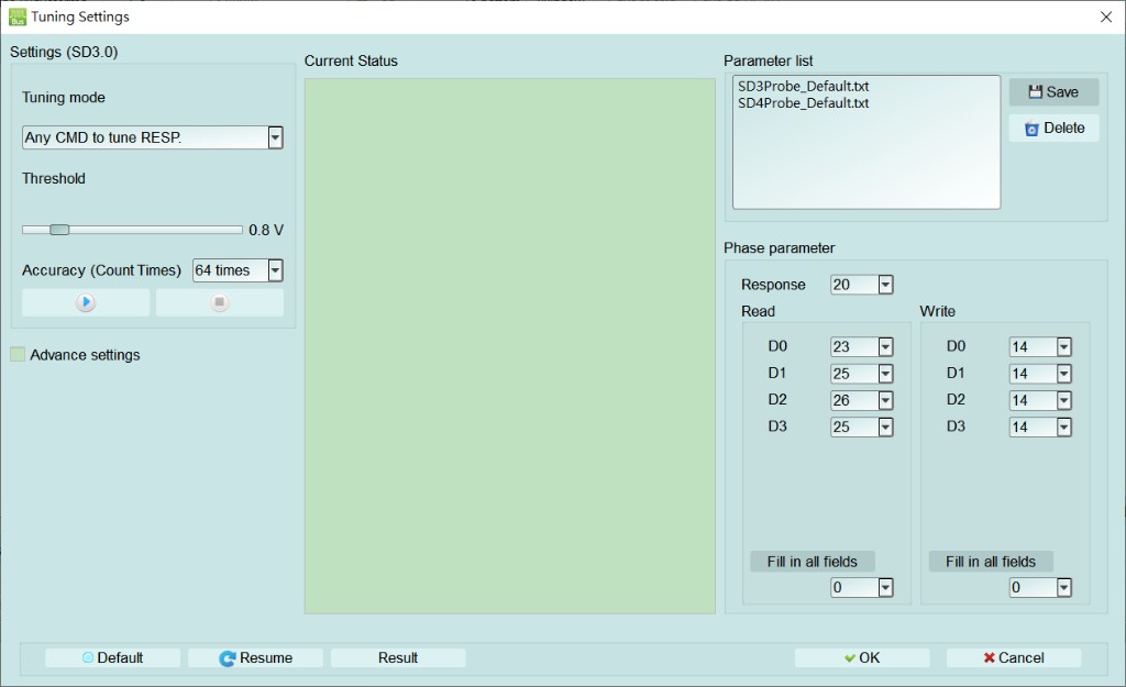
- Tuning settings: Opens Tuning Settings (see dialog below); set Tuning mode, Threshold, and Accuracy, and adjust Response / Read / Write (D0–D3) phase. Manage parameter files with Save / Delete.
- Vendor CMD: Opens Vendor CMD settings (see Settings — Vendor CMD settings).
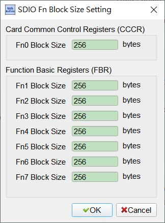
- SDIO Block Size / Enable SDIO Read Wait: Opens SDIO Fn Block Size Setting (see below) for Fn0–Fn7 block sizes; optionally enable SDIO Read Wait. Block Size Default for each Fn is 256 bytes; Read Wait Default cleared.
- CLK Detect: Detect CLK activity; time condition enabled (Enable) when checked. Default: cleared.
- Trigger settings:
- Trigger on: CMD/Resp/Data, End-bit/CRC7/CRC16/CRC status (with timeout), VDD Drop, etc. Children are enabled (Enable) when checked; CMD/Data open matching dialogs (see Settings links). Default: Trigger on and error items cleared.
- Command / Response: Opens Trigger Settings (see Settings — Trigger Settings).
- Data: Opens Data Trigger (see Settings — Data Trigger).
- VDD Drop: Voltage-drop trigger; open Voltage Range Settings (see Settings — Voltage Range Settings).
- Trigger on: CMD/Resp/Data, End-bit/CRC7/CRC16/CRC status (with timeout), VDD Drop, etc. Children are enabled (Enable) when checked; CMD/Data open matching dialogs (see Settings links). Default: Trigger on and error items cleared.
Open this dialog from Option → Tuning settings. Set Tuning mode, Threshold, and Accuracy, and adjust Response and Read / Write (D0–D3) phase. Manage parameter files with Save / Delete; use Resume / Result to continue calibration or view results.
Open this dialog from Option → SDIO Block Size. Set Block Size for CCCR Fn0 and FBR Fn1–Fn7 (Default 256 bytes each).