SD 4.0 (UHS-II) (Ultra High Speed II)
SD 4.0 (UHS-II) Protocol Analyzer settings.
Supported Models
BusFinder
All BF6000/BF7000 models are supported. This feature requires purchasing an additional option.
Settings
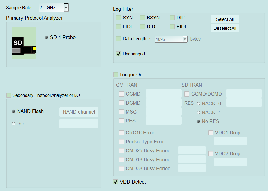
- Settings:
- Sample Rate: Select the sample rate. Default: 2 GHz.
- Primary Protocol Analyzer: SD 4 Probe for SD 4.0 (UHS-II).
- Secondary Protocol Analyzer or I/O: NAND Flash or I/O on remaining pins.
- Log Filter: Filter by packet type (SYN, BSYN, DIR, LIDL, DIDL, EIDL, …). When length filtering is checked, Data Length > is enabled (Enable). Default: packet types cleared, length filter cleared.
- VDD Detect: When checked, show VDD voltage in the report. Display only — no trigger capability (unlike Trigger On VDD1/VDD2 Drop). Default: checked. See also Settings — Voltage Detect.
- Trigger settings:
- Trigger On: When checked, child items are enabled (Enable); first check often opens the matching dialog (see dialogs below). Default: Trigger On and all children cleared.
- CM TRAN: CCMD / DCMD / MSG / RES triggers.
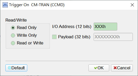
- CCMD: Opens Trigger On CM-TRAN (CCMD). Default: Read Only; I/O Address XXXh; Payload cleared (field disabled (Disable), typically XXXXXXXXh).
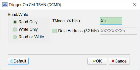
- DCMD: Opens Trigger On CM-TRAN (DCMD). Default: Read Only; TMode Xh; Data Address cleared (field disabled (Disable), typically XXXXXXXXh).
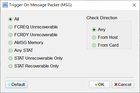
- MSG: Opens Trigger On Message Packet (MSG). Default: packet type All; Check Direction Any.
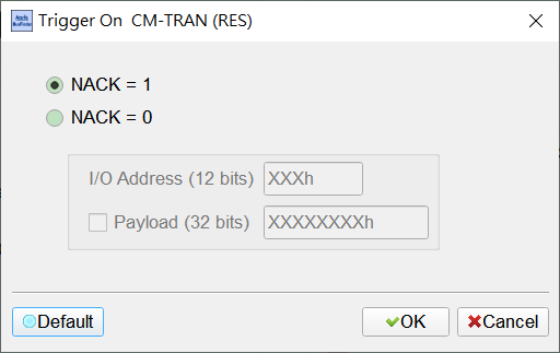
- RES: Opens Trigger On CM-TRAN (RES). Default: NACK = 1 (I/O Address / Payload then disabled (Disable)).
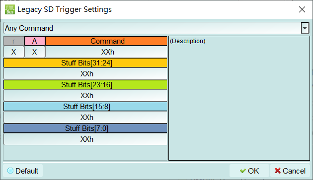
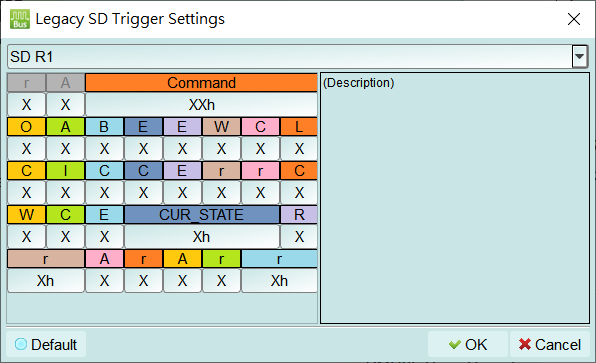
- SD TRAN: CCMD/DCMD and RES (NACK / No RES); command/response setup opens Legacy SD Trigger Settings. Choosing NACK may disable (Disable) the RES setup button. Default: No RES.
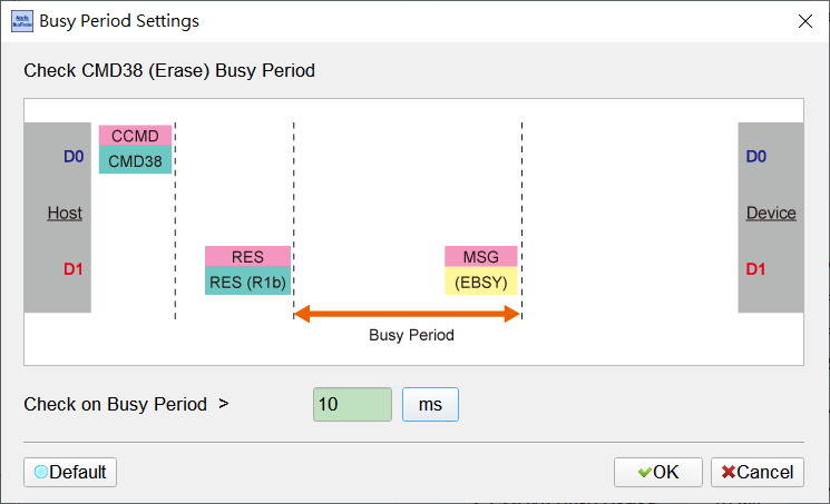
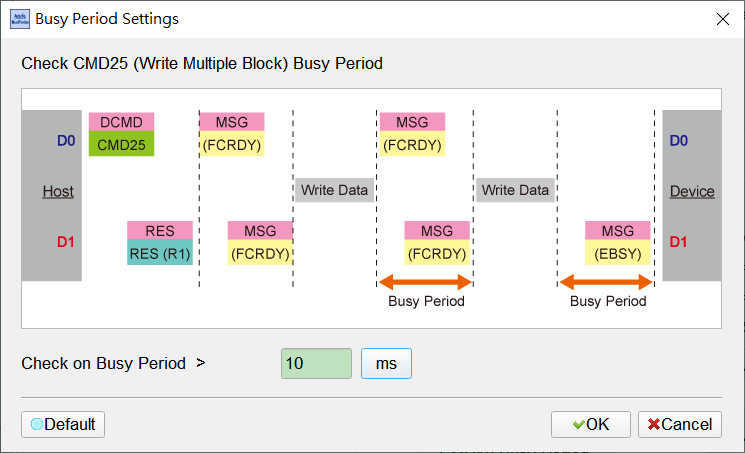
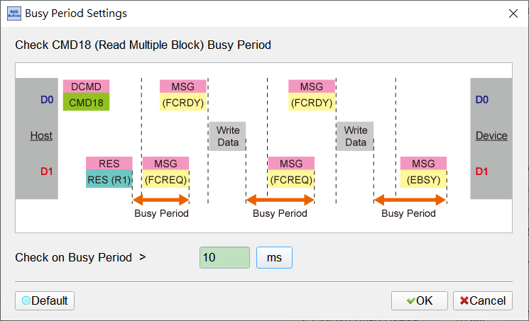
- Error / Busy / Voltage: CRC16, Packet Type Error, CMD25/18/38 Busy Period, VDD1/VDD2 Drop. Busy Period dialog Default about 10 ms. Default: all cleared.
- VDD1 Drop / VDD2 Drop: Voltage-drop trigger; open Voltage Range Settings (see Settings — Voltage Range Settings). Typical VDD1 about 2.70–3.60 V, VDD2 about 1.70–1.95 V.
- CM TRAN: CCMD / DCMD / MSG / RES triggers.
- Trigger On: When checked, child items are enabled (Enable); first check often opens the matching dialog (see dialogs below). Default: Trigger On and all children cleared.
Open this dialog from Trigger On → CM TRAN → CCMD. Choose Read Only / Write Only / Read or Write, and set I/O Address (12 bits). When Payload is checked, the 32-bit field is enabled (Enable). XXXh / XXXXXXXXh means don't care for that field.
Open this dialog from Trigger On → CM TRAN → DCMD. Choose Read / Write, set TMode (4 bits), and optionally enable Data Address (32 bits). Xh / XXXXXXXXh means don't care for that field.
Open this dialog from Trigger On → CM TRAN → MSG. Select a Message Packet type (All, FCREQ/FCRDY Unrecoverable, AMSG Memory, STAT, …) and filter by Check Direction (Any / From Host / From Card).
Open this dialog from Trigger On → CM TRAN → RES. Choose NACK = 1 or NACK = 0. With NACK = 1, I/O Address / Payload are disabled (Disable).
Open Legacy SD Trigger Settings when configuring an SD TRAN command. Choose Any Command (or a specific command) and combine r / A / Command / Stuff Bits fields. X / XXh means don't care for that field.
Open the same dialog for an SD TRAN response (for example SD R1). Combine R1 status bits and CUR_STATE. X / Xh / XXh means don't care for that field.
Open this dialog from Trigger On when CMD25 Busy Period is selected. The diagram shows the Write Multiple Block busy period; set Check on Busy Period > (Default about 10 ms).
Open this dialog from Trigger On when CMD18 Busy Period is selected. The diagram shows the Read Multiple Block busy period; set Check on Busy Period > (Default about 10 ms).
Open this dialog from Trigger On when CMD38 Busy Period is selected. The diagram shows the Erase busy period; set Check on Busy Period > (Default about 10 ms).