SafeSPI (Serial Peripheral Interface for Automotive Safety)
SafeSPI standardises the use of SPI for automotive sensor data. Plain SPI defines the electrical and clock relationship but nothing about the content — no address, no checksum, no status — so SafeSPI adds a logical layer on top of the same four wires: fixed 32-bit or 48-bit frames, a target address on the command and a source address on the response, a CRC on every frame, sensor status bits, and timing limits for the bus. This decode implements Rev 2.0, which is backward compatible with Rev 1.0 — the CRC definitions and test vectors are identical and 48-bit frames are the v2.0 addition, so no version selector is needed.
Decode Settings
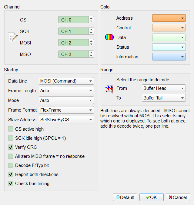
- Data Line: Select which line the waveform strip shows, MOSI (Command) or MISO (Response). Both lines are always decoded whichever is selected — SafeSPI is full duplex and the two lines' field boundaries do not align, so one strip cannot hold both. To see both as two strips, add this decode a second time set to the other line. The report is not restricted this way; see Report both directions below. Default: MOSI (Command).
- Frame Length: Select Auto, 32 Bit or 48 Bit. Auto counts the SCK cycles inside the chip-select window and cross-checks the CRC, which is the detection method the standard provides for this. The resolved width is shown in the report settings row as
32oof (Auto). Default: Auto. - Mode: Select Out-of-Frame (Mode 0), In-Frame (Mode 1) or Auto. Out-of-frame samples on the rising SCK edge and the slave's answer arrives in the next frame; in-frame samples on the falling edge and the answer is inside the same frame. Auto scores the CRC variants against both edge streams. Disabled when Frame Length is 48 Bit, which is out-of-frame only. Default: Auto.
- Frame Format: Select FlexFrame or FixedSensorFrame. This cannot be auto-detected: the two use the same bits and produce the same valid CRC, and differ only in whether those bits carry defined fields. FlexFrame leaves them free to use; FixedSensorFrame defines RW, CAP and DATAI on the command. Choosing Fixed for a Flex bus fabricates fields that do not exist, so the default is the safe one. Default: FlexFrame.
- Slave Address: Select how the target and source addresses split into a slave address and a slave-internal address: SelSlaveByCS (one chip select per slave), Sel2SlaveByAdrPin, Sel2SlaveByAdrNVM, Sel4SlaveByAdrPin or Sel4SlaveByAdrNVM. Default: SelSlaveByCS.
- CS active high: SafeSPI asserts chip select LOW. Check this if the capture was taken through an inverting probe or the device uses the opposite polarity. Default: unchecked.
- SCK idle high (CPOL = 1): SafeSPI idles the clock LOW. Check this for a bus that idles high; the sampling edge is normalised accordingly. Default: unchecked.
- Verify CRC: Check each frame's CRC. SafeSPI has four CRC variants — 32-bit out-of-frame, 32-bit in-frame command, 32-bit in-frame response and 48-bit — with different coverage ranges; the decoder selects the right one for each frame. The CRC cell is green when it matches and red when it does not. Default: checked.
- All-zero MISO frame = no response: Treat a response frame whose bits are all zero as the slave not answering, and report it instead of decoding the zeros. This is a derived rule rather than a stated one — it relies on the Rev 2.0 requirement for a MISO pull-down, which Rev 1.0 does not have — so it is off until a real capture confirms it. When on, the Information column states the evidence as
Assumed Hi-Z. Default: unchecked. - Decode FrTyp bit: Interpret the FrTyp bit as announcing the width of the next frame. This only applies to a device implementing the mixed 48/32-bit option with address-selected width; elsewhere the bit is free to use and announces nothing. The field itself is always shown — this setting only controls whether the interpretation is added to the Information column. Default: unchecked.
- Report both directions: List the command and the response in one report, two rows per frame, with a Dir column saying which is which. The waveform strip still shows the Data Line only. Turn it off for a single-direction report matching the strip. Default: checked.
- Check bus timing: Measure the bus against the timing tables of the standard — SCK high and low times, chip-select lead and lag, sequential transfer delay, and the setup, hold and valid times of both data lines. Violations are listed at the top of the report by requirement number with the measured worst value, the limit and where it happened. A limit the capture's sample rate cannot resolve is counted but never judged. Default: checked.
Result
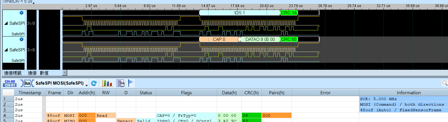
With Report both directions on, the report shows two rows per frame. Dir says whether the row is the command or the response, and the shared columns then hold whichever field that direction defines: Addr is the target address on a MOSI row and the source address on a MISO row, Data is DATAI or DATAO, and Flags carries CAP and FrTyp on a command row or IDS, CE and DCnt on a response row. D and Status apply to responses only.
Pairs shows the request/response relationship, which is not visible from row order alone: out-of-frame answers arrive one frame late, so the two rows of a single frame are not a pair. On a command row the cell names the source address of the response that came back; on a response row it names the target address of the command being answered. A blank cell means the counterpart was not observed — at the end of the capture, or before the first command — and a red dash means the command was seen to go unanswered.
The first report row always states the SCK frequency measured from the capture itself, followed by the settings the decode ran with. The CRC cell is green when the checksum matches and red when it does not. Notes that are not faults, such as a sensor in its initialisation state, go to the Information column rather than to Error.