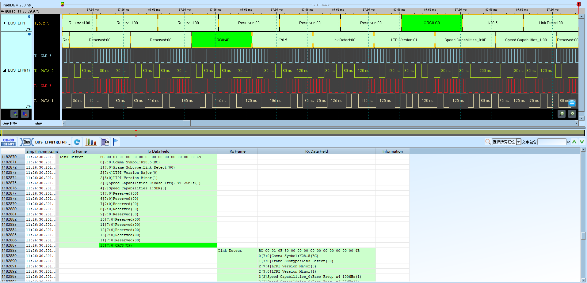
LTPI (LVDS Tunneling Protocol & Interface)
LTPI (LVDS Tunneling Protocol & Interface) carries low-speed signals between the HPM and SCM. It supports GPIO, I2C/SMBus, UART, and related channels via TDM over LVDS. GPIO has low- and normal-latency types; I2C/SMBus handles single-controller links; UART supports flow control; OEM is for proprietary interfaces; a data channel supports memory-mapped transfers.
Wrong Interface mode or waveform direction/type yields incorrect decode content. For channel-prefix differences, see Settings.
Decode Settings
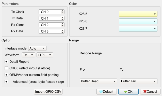
- Tx Clock / Tx Data / Rx Clock / Rx Data: Assign each signal to a logic analyzer channel.
- Interface mode: SDR / DDR / Auto. Default: Auto.
- Waveform: Direction and decode content in the waveform area.
- Direction: Tx / Rx. Default: Tx.
- Type: LTPI / GPIO / Uart 0–1 / I2C 0–5 / 8b10b. Default: LTPI.
- Detail Report: Detailed report. Field enabled (Enable) when checked. Default: checked.
- CRC8 reflect in/out (Lattice): CRC-8 (0x07) reflect in/out. Field enabled (Enable) when checked. Default: cleared.
- OEM/Vendor custom-field parsing: Parse OEM/vendor fields from
AqLTPI_Vendor.csvin the working directory. Field enabled (Enable) when checked. Default: checked. - Advanced (cross-byte / scale / signed / little-endian): Advanced field parsing. Field enabled (Enable) when checked. Default: checked.
- Import GPIO CSV: Import GPIO bit names from CSV.
Result