JTAG (Joint Test Action Group)
JTAG (Joint Test Action Group) is an international test protocol (IEEE 1149.1) for on-chip testing; many advanced devices (DSP, FPGA, etc.) support it. Interfaces: TCK, TMS, TDI, TDO, and TRST (TDO is output). A TAP (Test Access Port) is defined inside the device and exercised with a JTAG tool.
With cJTAG enabled, TDI/TDO are field disabled (Disable); TCK/TMS act as TCKC/TMSC in OScan1. Instruction decode may decide whether TRST is required. See Settings.
Decode Settings
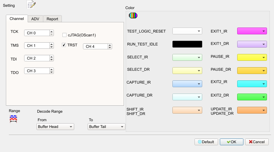
- Channel: Assign TCK / TMS / TDI / TDO / TRST. TRST is optional; field enabled (Enable) when checkedchecked.
- cJTAG: Disables TDI/TDO fields; TCK/TMS as TCKC/TMSC. Default: cleared.
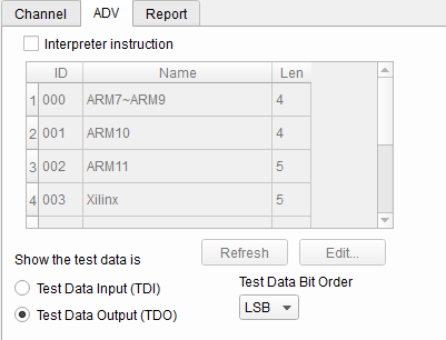
- Show test data: In Shift-IR / Shift-DR, show TDI or TDO in hex. Default: show TDO.
- Test data bit order: LSB First / MSB First. Default: index 0 (LSB First).
- Interpreter Instruction: Enable the instruction list; show IR contents at Update-IR. Edit
JtagInst.txt, then Refresh. Default: checked. - Acute Jtag Instruction table (JtagInst.txt): Provided by the Jtag DLL; editable; BSDL can be added. See appendix.
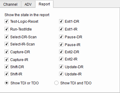
- Show TDI or/and TDO: “Show TDI and TDO” shows both. Default: Show 1 data.
- TAP state display: Default: all states checked.
Result
Appendix: Acute JTAG Instruction table (JtagInst.txt)
Numbers are hexadecimal.
- ##: comment
- #ID: list ID 00–FF; must be sequential
- #NAME: set name (max 32 bytes)
- #LENGTH: instruction length in bits
- #CAPTURE: Capture-IR value
- #INST: code, name; empty
#INST:ends the list - #TRST: 1 if TRST needed; 0 or omit if not
- #BSDL: full BSDL path
Example: same as the traditional sample (#ID:00 … #BSDL:C:\3256at144_1532.bsd).