ADC (Analog-To-Digital Converter)
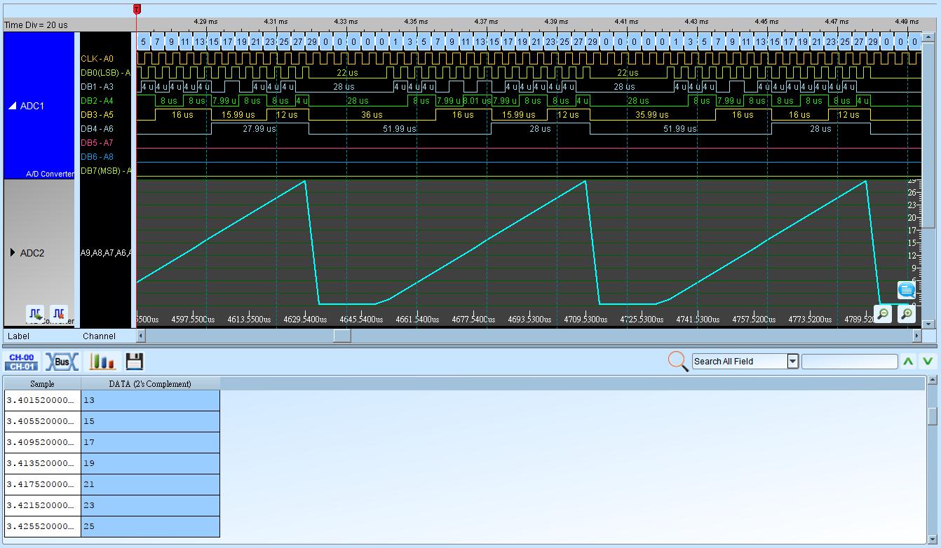
An A/D Converter (Analog-To-Digital Converter) samples a continuous quantity into a discrete digital representation.
See Settings for channel prefixes.
Decode Settings
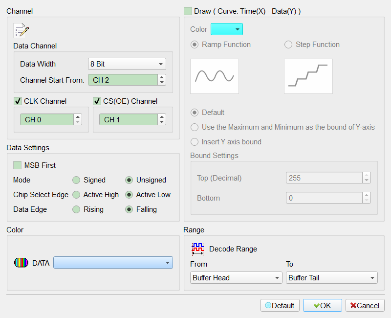
- Data Channel Start From: Starting channel for ADC data bits.
- CLK Channel: ADC CLK IN. Field enabled (Enable) for CLK and Data Edge when checkedchecked.
- CS(OE) Channel: Chip Select. Field enabled (Enable) for CS and Chip Select Edge when checkedchecked.
- Data Width: 4 Bit–32 Bit. Default: 4 Bit.
- MSB First: Data starts from MSB; cleared means LSB. Field enabled (Enable) when checked. Default: cleared (LSB).
- Chip Select Edge: Active High / Active Low. Default: Active Low.
- Data Edge: Rising / Falling. Default: Falling.
- Signed / Unsigned: Default: Unsigned.
- Curve: Time(X)–Data(Y): Plot curve. Field enabled (Enable) when checked. Default: cleared.
- Ramp / Step Function: Curve style. Default: Ramp.
- Color: Curve color.
- Bound Value Range:
- Default: Y bounds from data-width min/max. Default: this mode selected.
- Use max/min data as Y bounds: Use observed data extremes.
- Insert Y axis bound: Enter Y bounds manually.
Result
8-bit data with CLK/CS:
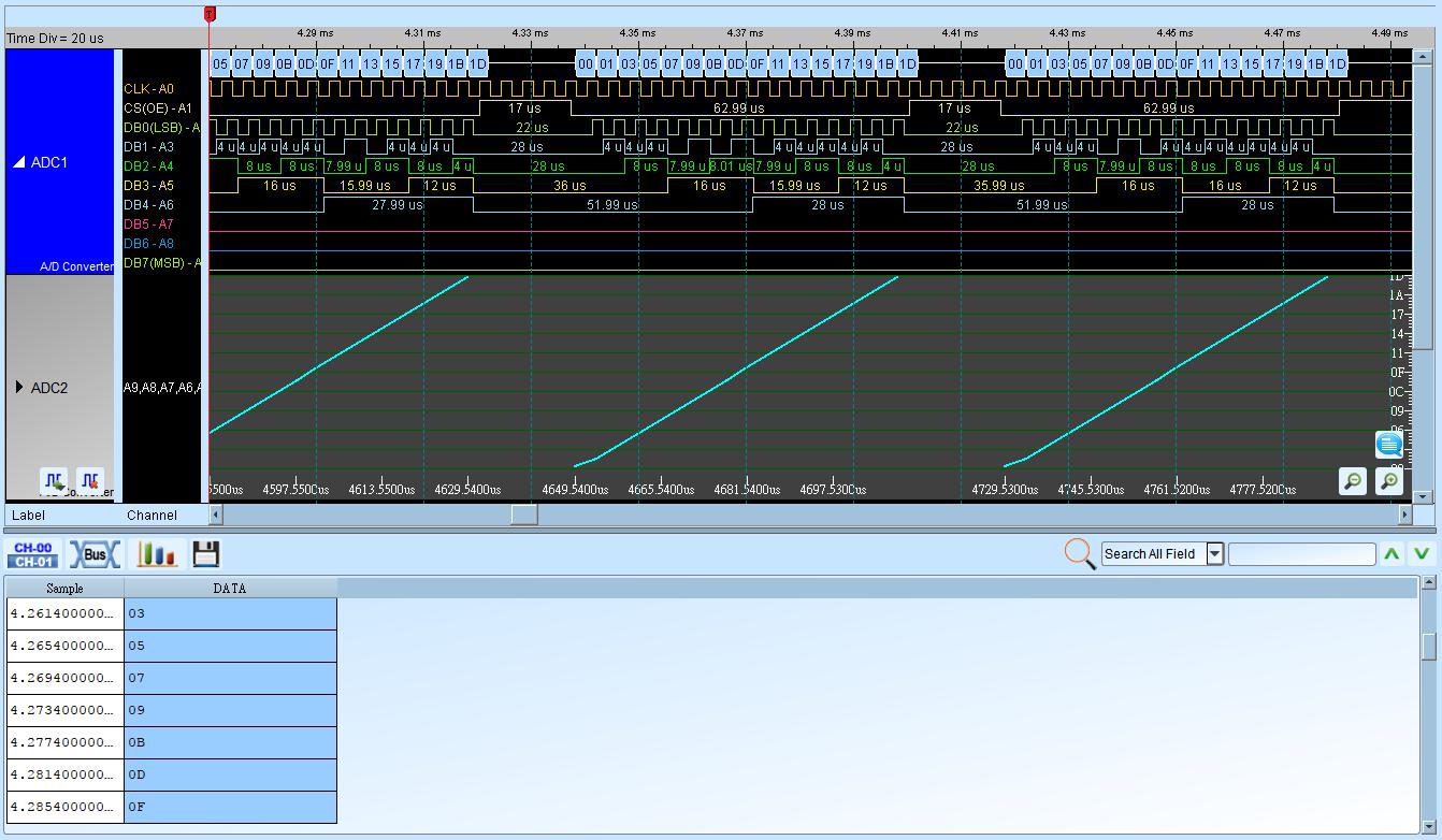
8-bit data with CLK: