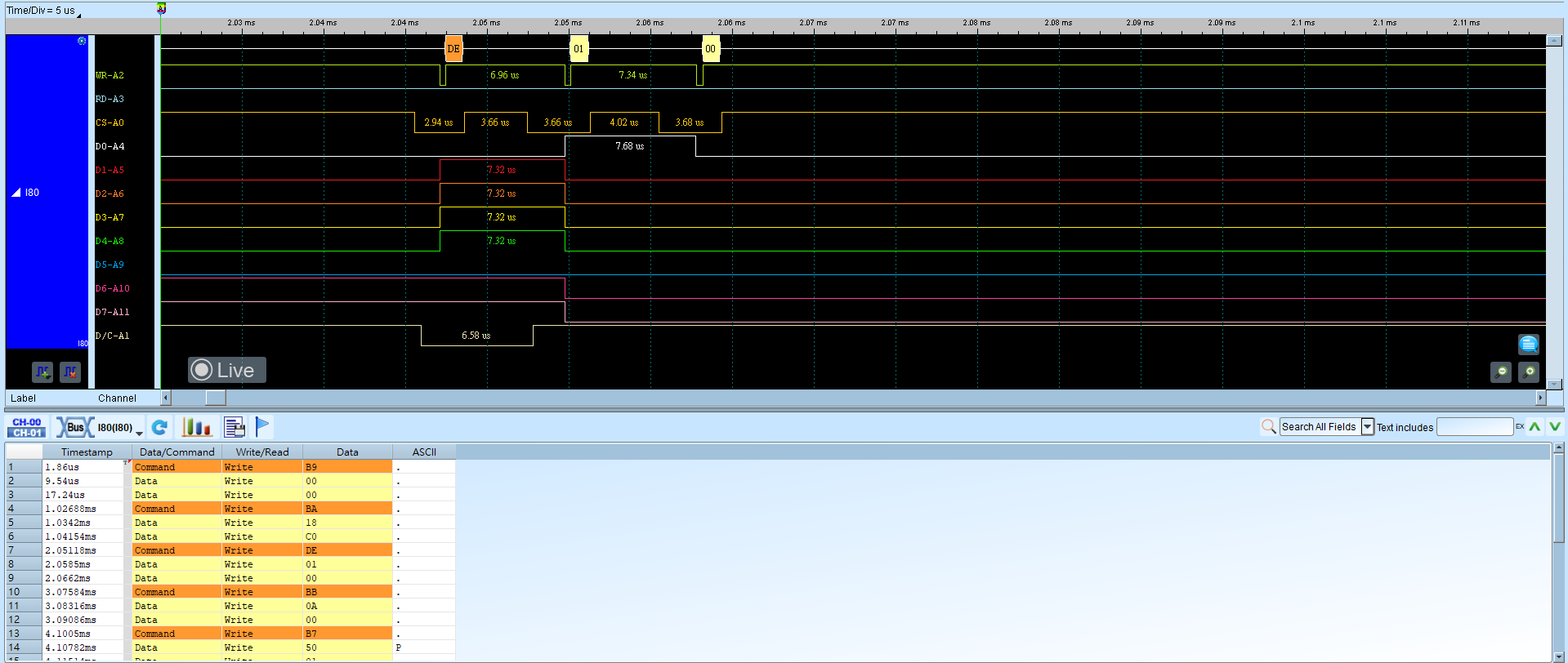
I80 (Intel 8080)
The Intel 8080-series interface is mainly used for LCM data transfer (I80 interface). Analyzing 8080-series requires 3 or 4 control lines (WR, RD, CS, and optionally D/C) and a data bus of at least 4 bits, so at least 7 channels are needed (WR, RD, CS, D0–D3); with D/C, 8 channels. An 8-bit data bus needs 11 signals (WR, RD, CS, D0–D7), and so on. Channel numbers can be adjusted.
Wrong Data Bus / Bit Order or On D/C settings cause decode failures. For channel-prefix differences, see Settings.
Decode Settings
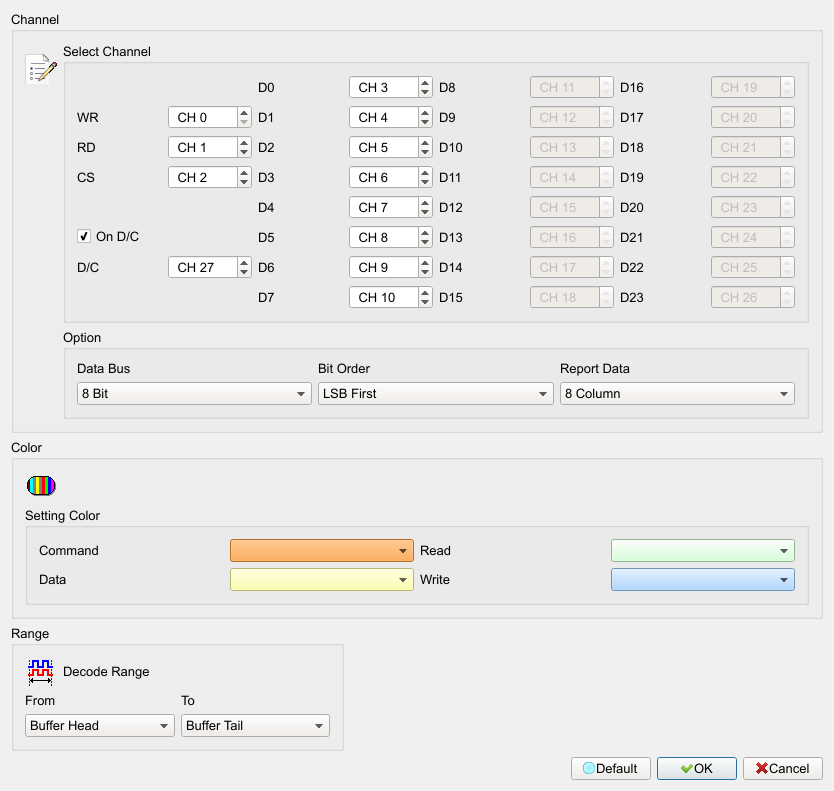
- Select Channel: Assign Logic Analyzer channels for WR, RD, CS, and DATA pins.
- On D/C: Use the D/C pin as Command (Low) or Data (High). When checked, the D/C channel and Cmd/Data colors are enabled (Enable); when cleared, those fields are disabled (Disable). Default: checked.
- Data Bus: DATA pin width (4 / 8 / 12 / 16 / 20 / 24 Bit). Default: 8 Bit. Wider buses enable (Enable) matching D* channels; unused channels are disabled (Disable).
- Bit Order: LSB First or MSB First. Default: LSB First.
- Report Data: Columns per report row (8 Column / 16 Column). Default: 8 Column.
Result