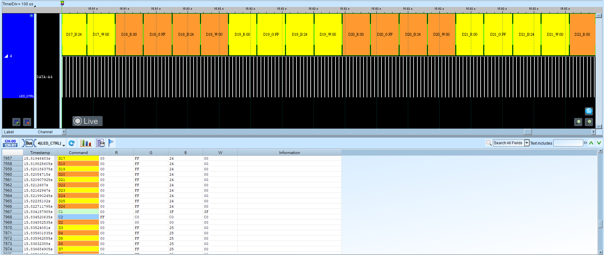
LED_CTRL (LED Driver TM1814)
LED Controls target digital LEDs with on-chip drivers so an MCU can drive a single LED or a section of LEDs.
Wrong Model, timing (T0 / T1 / Reset), or Bit Size yields decode failure; non-Custom models often field-disable (Disable) timing fields. For channel-prefix differences, see Settings.
Decode Settings
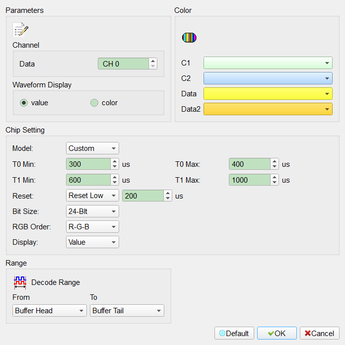
- Channel (Data): Assign the LED data signal channel.
- Waveform Display: Show decode as numeric values or RGB color in the waveform.
- value: Show numeric values. Default: this mode selected.
- color: Show RGB color.
- Chip Setting:
- Model: IC model (Custom, TM1814, WS2811, WS2812, RT7905, HZ0028). Non-Custom often field-disables (Disable) T0 / T1 / Reset / Bit Size and applies that model’s preset. Default: Custom.
- Timing (Idle high): Waveform idle is high. A low pulse between T0 Min and T0 Max decodes as 0; between T1 Min and T1 Max as 1. Custom Default: T0 Min 300 µs, T0 Max 400 µs, T1 Min 600 µs, T1 Max 1000 µs.
- Reset: Holding high longer than the set time resets the start bit (Reset High / Reset Low). Custom Default: Reset High, 200 µs.
- Bit Size: 24-Bit (RGB) / 32-Bit (WRGB) / 48-Bit. Default: 24-Bit.
- RGB Order: RGB byte order. Default index: 0.
- Display: Value / Percentage (tied to waveform display). Default: Value.
Result