PWM (Pulse-width modulation)
PWM (Pulse Width Modulation) is not a bus analysis protocol. It is a technique that controls analog circuits by varying pulse width, widely used for rotational speed, brightness, and temperature control.
For channel-prefix differences, see Settings.
Decode Settings
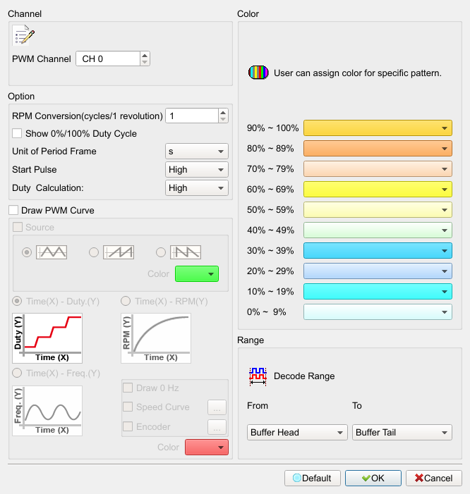
- PWM Channel: PWM signal channel.
- RPM Conversion (Cycles/1 Revolution): Number of PWM cycles per revolution. Default: 1.
- Show 0% and 100% Duty Cycle: When plotting Time (X)–Duty (Y), draw the 0% and 100% segments when checked; consecutive 0%/100% pairs are not drawn. Field enabled (Enable) when checked. Default: cleared.
- Unit of Period Frame: Time unit: s / ms / us. Default: s.
- Draw PWM curve: Draw PWM curves in the waveform area. Field enabled (Enable) when checked. Default: cleared.
- Source: Show the PWM source waveform. Field enabled (Enable) when checked. Default: cleared.
- Time(X)–Duty(Y): Plot time vs duty. Default: this mode selected.
- Time(X)–Freq.(Y): Plot time vs frequency.
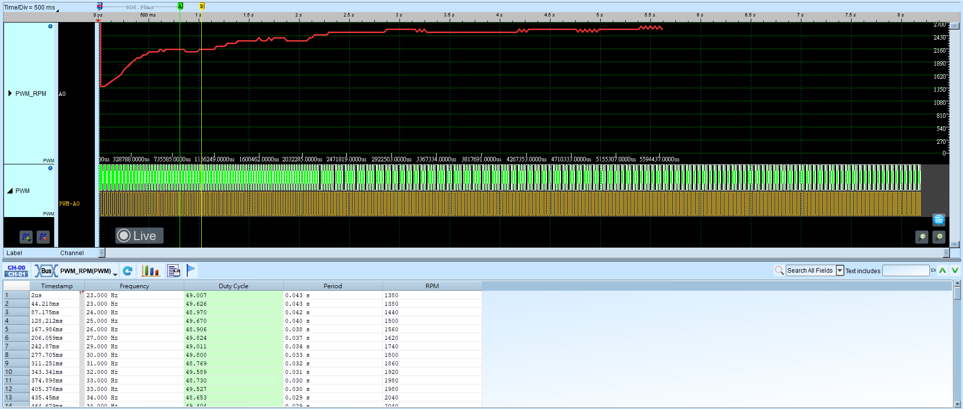
- Time(X)–RPM(Y): Plot time vs RPM.
- Draw 0 Hz: When Time(X)–Freq.(Y) is selected, start the Y axis at 0 Hz when checked. Field enabled (Enable) when checked. Default: cleared.
- Speed Curve: Supports up to three curves for overlay plotting. Field enabled (Enable) when checked. Default: cleared.
Speed Curve dialog (when Speed Curve is enabled):
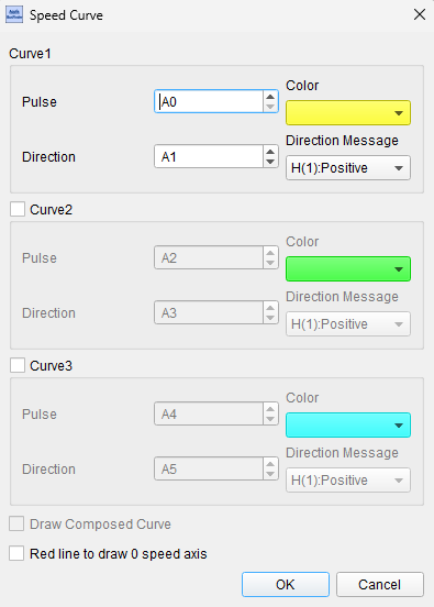
- Pulse/Direction: Pulse and direction channels on the instrument (up to three Curves).
- Direction Message: Direction source: H(1):Positive or L(0):Positive.
- Draw Composed Curve: Overlay composed curves when more than one Curve is enabled. Field enabled (Enable) when checked. Default: cleared.
-
Red line to draw 0 speed axis: Draw a red line where speed is 0. Field enabled (Enable) when checked. Default: cleared.
-
Encoder: Encode the PWM parse result. Field enabled (Enable) when checked. Default: cleared.
Result
Select Time(X)–Duty(Y):
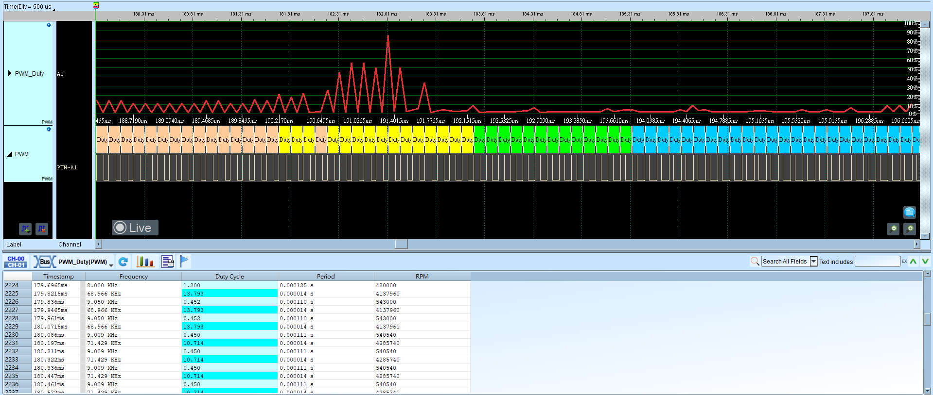
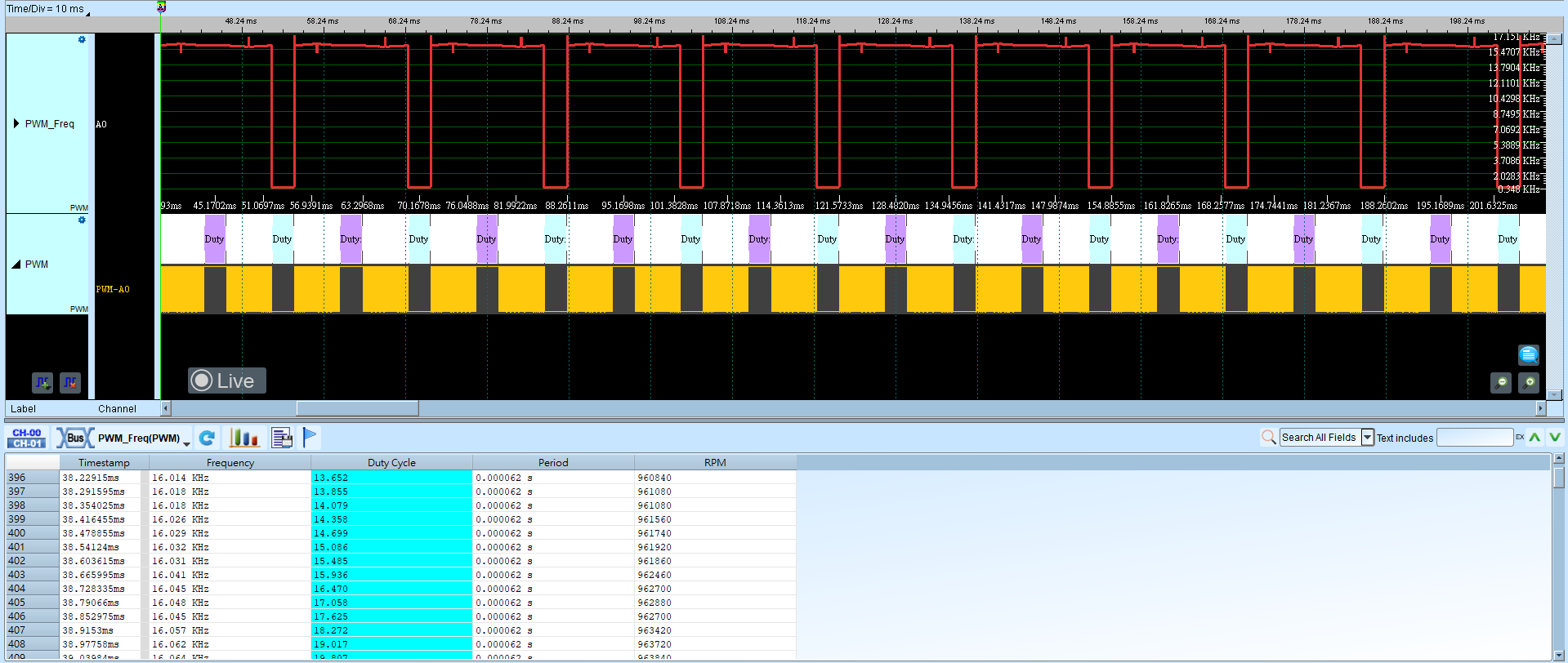
Select Time(X)–Freq.(Y):
Select Time(X)–RPM(Y):