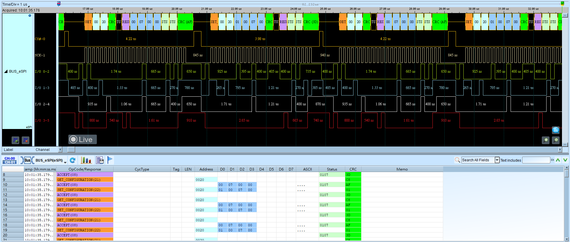
eSPI (Enhanced Serial Peripheral Interface)
eSPI is used on newer Intel baseboards to integrate SMBus / LPC / SPI Flash interfaces, simplifying the bus and improving throughput. Based on Enhanced Serial Peripheral Interface (eSPI) Interface Base Specification (for Client and Server Platforms) June 2013, Revision 0.75.
For channel-prefix differences, see Settings.
Decode Settings
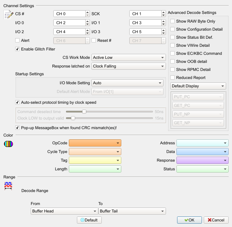
- Channel:
- CS#: Chip Select (Active Low).
- SCK: Clock.
- I/O0–I/O3: Data input / output.
- Alert: Optional Alert signal. Field enabled (Enable) channel and Alert Mode when checked. Default: cleared.
- Reset: Optional Reset signal. Field enabled (Enable) when checked. Default: cleared.
- Startup Settings:
- I/O Mode: Initial I/O state: Single / Dual / Quad / Auto; later switched automatically from the waveform. Default: Auto.
- Alert Mode: Whether early Alert comes from I/O1 or Alert#. Default: From I/O[1].
- Command deselect time: tSHSL (Chip Select# Deassertion Time). Default: 50 ns.
- Clock LOW to output valid: tCLQV (Output Data Valid Time). Default: 15 ns.
- Advanced Decode Setting:
- Show Configuration Detail: Show SET_CONFIG / GET_CONFIG details. Field enabled (Enable) when checked. Default: cleared.
- Show Status Bit Def.: Show Status details. Field enabled (Enable) when checked. Default: cleared.
- Reduced Report: Reduce report content to review Command Flow. Field enabled (Enable) when checked. Default: cleared.
- Filter Setting: Show or hide specific OP Code / Cycle Type or Address range. Default: Default Display. Address Filter settings are saved as
LA\eSPI\eSPIFilterX.binunder the work directory.
Result