Serial Flash (OSPI)
Serial flash (SPI Flash) 25, 35, and similar series use SPI/QPI/OPI as their data-transfer protocol. Serial flash bus analysis lets you view commands and input/output bus messages together, saving time versus analyzing waveforms with a generic SPI decode.
Incorrect Manufacturer/device, startup mode, or tCLQV/tSHSL settings cause command-parse failures. For channel-prefix differences, see Settings.
Decode Settings
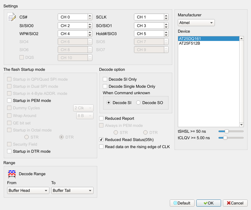
- CS#: Chip Select of the transfer signal.
- SCLK: Clock of the transfer signal.
- SIO0–SIO7: Data pins of the transfer signal.
- Manufacturer: Select the correct Flash model, tCLQV, and tSHSL for command parsing. If no exact model exists, choose a command-compatible model. Default is the first manufacturer/device entry.
- The Flash Startup Mode: Serial Flash can switch modes by command; when waveforms are captured, the analyzer does not know the current mode, so the user must set it when needed. Options unsupported by the selected model are disabled (Disable).
- QPI Mode: Quad Peripheral Interface Mode (Quad SPI Mode). Field enabled (Enable) when checked. Default is unchecked.
- 4-Byte Mode: 4-Byte Address Mode. Field enabled (Enable) when checked. Default is unchecked.
- PEM Mode: Performance Enhancement Mode. Field enabled (Enable) when checked. Default is unchecked.
- Dummy Cycles: Preset Dummy-cycle count for some Read commands. Field enabled (Enable) when the related option is checked.
- Wrap Around: Preset Wrap-around value. Field enabled (Enable) when the related option is checked.
- QE bit: QE bit in the status register for QPI enable/disable. Field enabled (Enable) when checked. Default is unchecked.
- Startup in Octal Mode: OPI mode; STR/DTR become enabled (Enable) when Octal is checked. Default is unchecked.
- Security Field: AES encrypt/decrypt Flash support; contact us if needed. Field enabled (Enable) when checked. Default is unchecked.
- Decode SI Only: Analyze in Single mode with 3 wires (CS# / SCLK / SI). Field enabled (Enable) when checked. Default is unchecked.
- Decode Single Mode Only: Analyze in Single mode with 4 wires (CS / Clock / SI / SO) and ignore multi-line switch commands; when unchecked, analyze as 4-wire or 6-wire per Flash model. Field enabled (Enable) when checked. Default is unchecked.
- When Command Unknown: Decode SO or SI only. Default is SI only.
- Always in PEM Mode: Stay in PEM regardless of commands; choose STR or DTR. Field enabled (Enable) when checked (enables STR/DTR). Default is unchecked.
- Reduce Read Status (05h): Merge repeated Read Status (05h) with unchanged data and show the repeat count. Field enabled (Enable) when checked. Default is unchecked.
- Read Status: Parse Read Status. Field enabled (Enable) when checked. Default is checked.
- Read data on the rising edge of CLK: For SDR Read Data, if Clock duty is unstable and tCLQV still cannot latch Data out correctly, latch on the next rising edge. Field enabled (Enable) when checked. Default is unchecked.
- DQS: Enable DQS. Field enabled (Enable) when checked. Default is unchecked.
- Enable DTR: Enable DTR. Field enabled (Enable) when checked. Default is unchecked.

Result
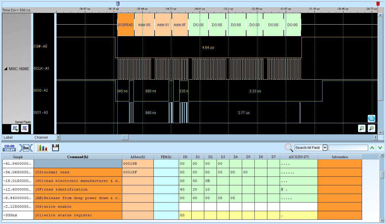
Using SPI Mode Serial Flash decoding:
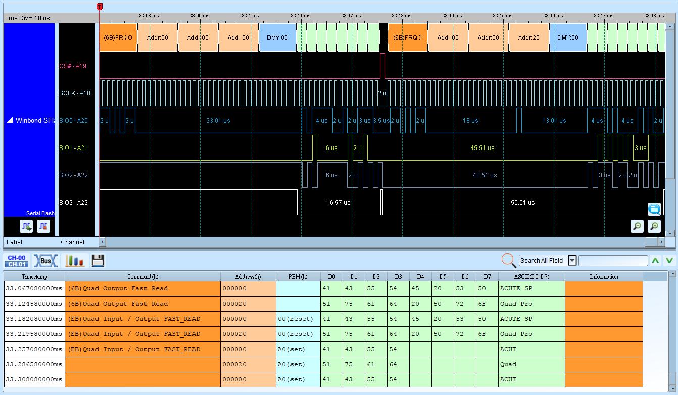
Using QPI Mode Serial Flash decoding:
Serial Flash data Comparison
Method: Create a text file named SFCmp.cfg to compare against real Serial Flash waveforms. Default path: “My Documents\Acute”.
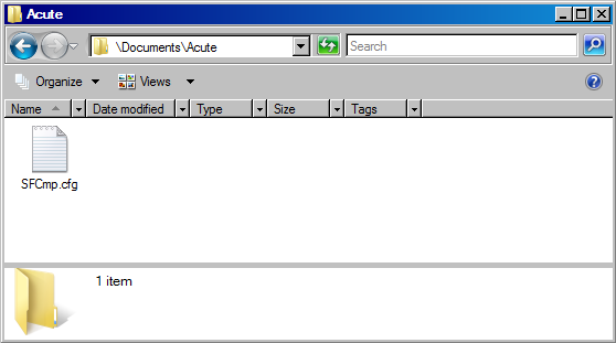
SFCmp.cfg information:
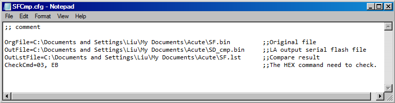
• OrgFile=File_Path: Path of the original Serial Flash data file (.bin).
• OutFile=File_Path: Path of the Serial Flash output file.
• OutLstFile=File_Path: Path of the comparison result (.lst).
• CheckCmd=Serial Flash command: Hex commands separated by commas.
Place the OrgFile at the OrgFile path:
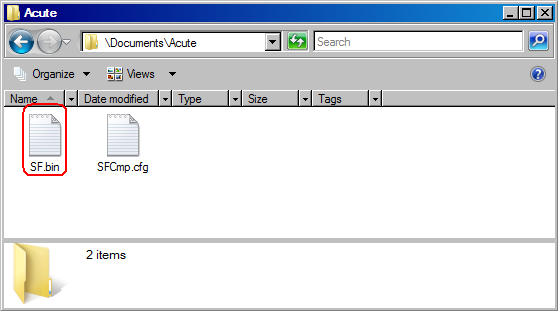
Run Serial Flash Protocol Decode to capture the Serial Flash signal. If OutFile does not exist, the tool copies OrgFile to OutFile and writes data according to CheckCmd.
Compare result:
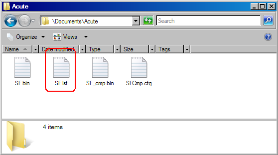
The OutLstFile:
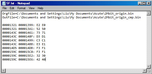
The first column is the compared address from OrgFile; the second column is the different address from OutFile.