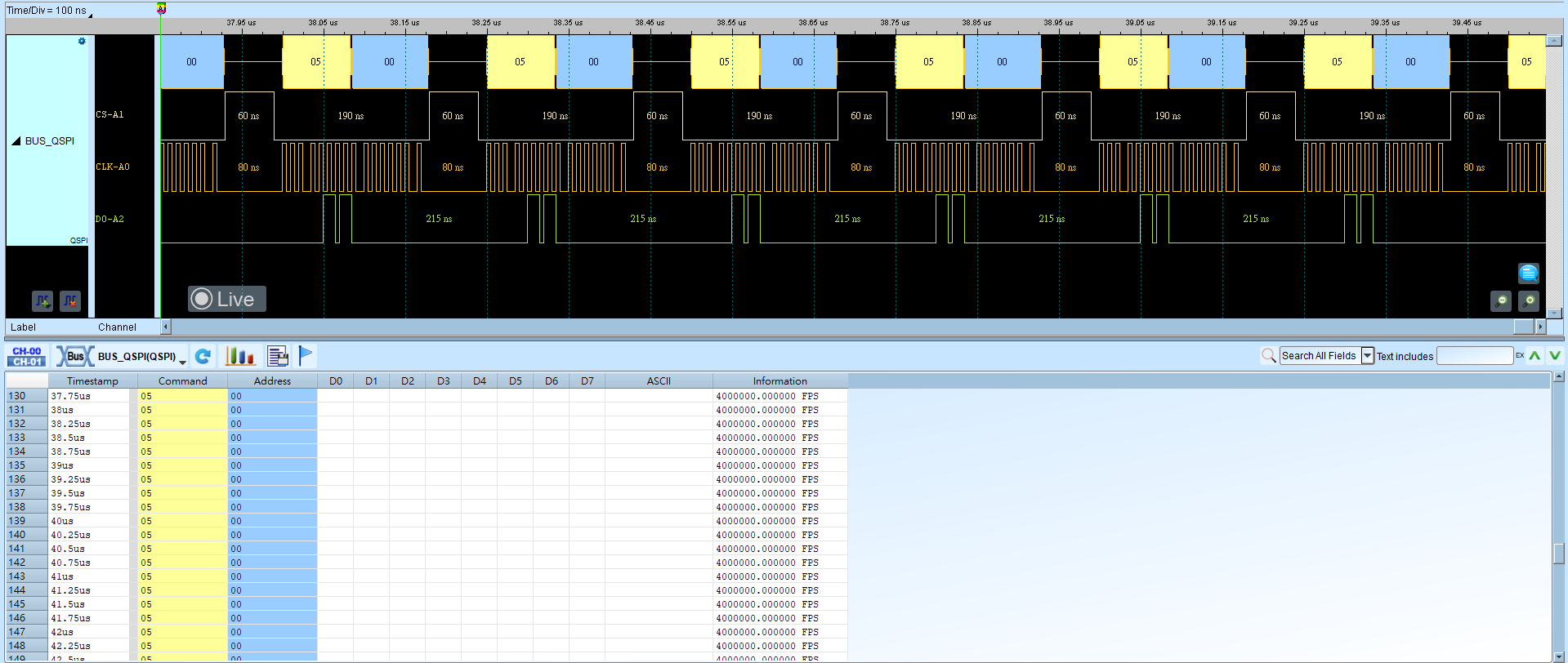
QSPI (Queued Serial Peripheral Interface)
QSPI is an enhanced version of SPI that increases DATA throughput with additional data lines. QSPI data lines are bidirectional and use parallel transfer.
Wrong CS, Latch Edge, Bus Width, or bit order yields incorrect frames. For channel-prefix differences, see Settings.
Decode Settings
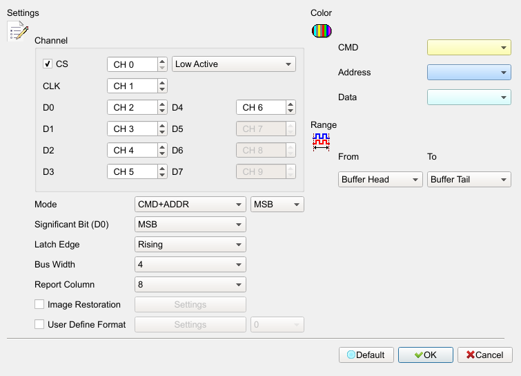
- Channel:
- CS: Chip select. When enabled, capture starts on the CS active edge. Field enabled (Enable) when checked. Default: checked, Low Active.
- CLK: Clock channel.
- D0–D7: Data channels (count depends on Bus Width).
- Mode: CMD+ADDR / CMD / DATA. Default: CMD+ADDR.
- Significant Bit (D0) / CMD MSB: MSB or LSB for data (and CMD) arrangement. Example Bus Width = 4 MSB: D0 D1 D2 D3…; LSB: D3 D2 D1 D0…. Default: MSB.
- Latch Edge: Rising / Falling / Both. Default: Rising.
- Bus Width: 1 / 2 / 4 / 8 data lines. Default: 4.
- Report Column: 8 / 16 columns in the report. Default: 8.
- Image Restoration: Save decoded waveform as an image; can load an extra config file. Field enabled (Enable) when checked. Default: cleared.
- User Defined Format: User-defined parse format; can load an extra config file. Field enabled (Enable) when checked. Default: cleared. Image Restoration and User Defined Format cannot be enabled at the same time.
Result