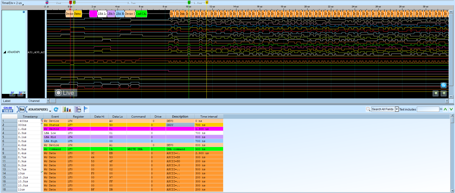
IDE (Integrated Device Electronics)
IDE (Integrated Device Electronics) is a standard interface for hard disks, solid-state drives, CD-ROMs, and similar storage. The name was first used by Western Digital in the U.S. for hard-disk sales. The official specification is ATA/ATAPI (Advanced Technology Attachment / AT Attachment Packet Interface). ATA continued to expand as capacity and transfer-speed needs grew. In 1998, ATA-4 added ATAPI so ATA could connect optical drives and other media. In 2003, SATA (Serial ATA) was published, and the original parallel ATA was retrospectively renamed PATA (Parallel ATA).
Because IDE is parallel, many channels are required. They are grouped into three types:
Normal channel (11 pin): DASP-, DIOR-:HDMARDY-:HSTROBE, DIOW-:STOP, DMACK-, DMARQ, INTRQ, IORDY:DDMARDY-:DSTROBE, PDIAG-:CBLID-, RESET-, CSEL, and IOCS16-.
Register channel (5 pin): CS(0:1)- and DA(2:0).
Data channel (16 pin): DD(15:0).
Recommended IDE bus wiring to the Logic Analyzer:
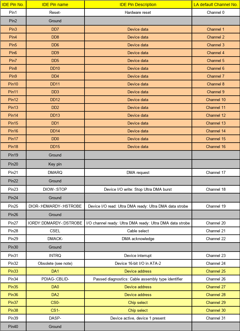
Wrong Transferring Mode may affect command interpretation; analysis can still run if not specified correctly. For channel-prefix differences, see Settings.
Decode Settings
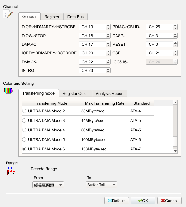
- Channel: Assign channel numbers on three pages (General, Register, and Data Bus).
- Transferring Mode: Specify which specification the device under test uses so IDE analysis can interpret commands correctly. If not specified correctly, analysis can still run. Default: ULTRA DMA Mode 6. With UDMA Mode 6, the IOCS16 channel is disabled (Disable).
- Analysis Report: Choose which registers appear in the report window. For example, if Data Register is cleared, data-register content is filtered out of the report. Field enabled (Enable) when checked. Default: all checked (Command, Alternate, Status, Sector Count, LBA Low/Mid/High, Features, Error, Dev Ctrl, Device, Data).
Result