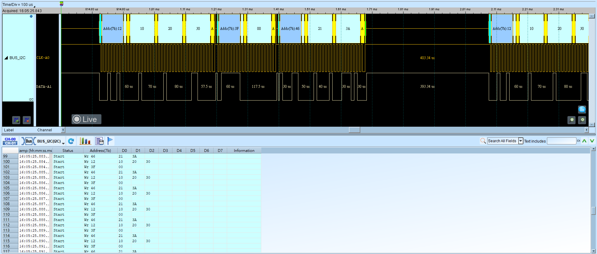
I2C (Inter-Integrated Circuit)
I2C (Inter-Integrated Circuit) is a two-wire serial bus with a multi-master/multi-slave architecture, introduced by Philips in the 1980s for connecting low-speed peripherals. It uses SCL (clock) and SDA (data). Frames include Start, Address, Data, and Read/Write; address modes are commonly 7-bit / 8-bit (R/W included) / 10-bit.
Wrong SCL/SDA wiring or address mode yields incorrect addresses in the report. For channel-prefix differences, see Settings.
Decode Settings
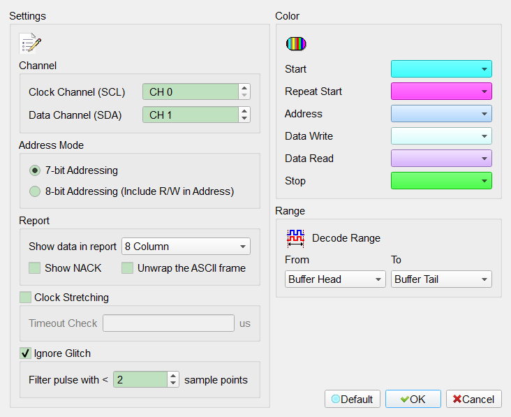
- Clock Channel (SCL): Assign the I2C clock (SCL) channel.
- Data Channel (SDA): Assign the I2C data (SDA) channel.
- Address Mode:
- 7-bit Addressing: Show a 7-bit address and 1-bit Rd/Wr. Default: this mode selected.
- 8-bit Addressing (Include R/W in Address): Show an 8-bit address (7-bit address plus 1-bit Rd/Wr).
- 10-bit Addressing: Show a 10-bit address.
- Report:
- Show data in report: Data columns in the report (8 Column / 16 Column). Default: 8 Column.
- Show NACK: Mark that byte as NACK. Field enabled (Enable) when checked. Default: cleared.
- Unwrap the ASCII frame: Add an ASCII column in the report. Field enabled (Enable) when checked. Default: cleared.
- Clock Stretching: Detect clock stretching. Field enabled (Enable) when checked. Default: cleared.
- Ignore Glitch: Ignore short glitches. Field enabled (Enable) when checked. Default: checked, < 2 sample points.
Result
- Wr: Write data
- Rd: Read data