CXPI (Clock Extension Peripheral Interface)
CXPI is an automotive single-wire network standardised as ISO 20794 (from JASO D015, via SAE J3076). It sits between LIN and CAN and is used for body and HMI networks — switches, sensors, actuators and instrument clusters. The master node embeds its clock in the data waveform through PWM encoding, which is where the name comes from, so slave nodes need no crystal; slaves may also transmit on their own initiative, which LIN cannot do. The bus runs at 2.4 to 20 kbit/s as a single-ended bus, with recessive HIGH and dominant LOW and non-destructive bit arbitration.
Decode Settings
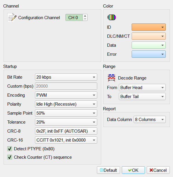
- Configuration Channel: Select the logic analyzer channel the CXPI bus is connected to. CXPI uses a single wire, so only one channel is needed.
- Color: Set the background color of the ID, DLC/NM/CT, Data and Error fields. Default: ID orange, DLC/NM/CT peach, Data light green, Error light blue.
- Bit Rate: Select 20, 19.2, 10, 9.6, 4.8 or 2.4 kbps, Custom, or Auto. Auto automatically detects the signal bit rate. The detected rate is shown in the report Information column. If no plausible CXPI rate is found, decoding falls back to 20 kbps and reports
Auto, not detected. Default: 20 kbps.- Custom (bps): Enter any bit rate in bit/s. Enabled only when Bit Rate is set to Custom. Default: 20000.
- Encoding: Select the line coding. PWM starts every bit with a falling edge that carries the clock — logic 1 is a short dominant pulse (25 %) and logic 0 a long one (75 %). NRZ holds the level for the whole bit. Both are sampled at mid-bit. Default: PWM.
- Polarity: CXPI idles recessive HIGH. Select Idle Low (Inverted) if the capture was taken through an inverting probe. Default: Idle High (Recessive).
- Sample Point: Position of the sample moment inside a bit, 20 % to 80 %. 50 % suits both line codings. Default: 50 %.
- Tolerance: Permitted deviation of the measured bit width from the selected bit rate, 5 % to 50 %. Raise it for a signal with a loose clock. Default: 20 %.
- CRC-8: Generator polynomial used for the normal frame checksum. Select None to skip the check. Default: 0x2F, init 0xFF (AUTOSAR).
- CRC-16: Initial value used for the long frame checksum (CCITT 0x1021). Select None to skip the check. Default: CCITT 0x1021, init 0x0000.
- Detect PTYPE (0x80): Treat a leading 0x80 byte as the PTYPE byte of the polling method. The byte is excluded from the CRC and is reported in the Information column. Default: checked.
- Check Counter (CT) sequence: Verify that the CT field advances by one (modulo 4) between two frames carrying the same frame ID, so a lost or duplicated frame becomes visible. A break is reported as a Counter error. Default: checked.
- Data Column: Number of payload columns in the report, 8 (D0..D7) or 16 (D0..D15). A frame with more data bytes than this wraps onto continuation rows, so a long frame carrying up to 255 bytes stays readable. Default: 8 Columns.
Result
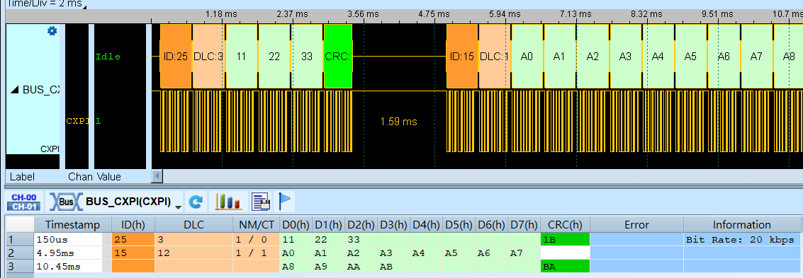
The report shows one row per frame: ID, DLC, NM/CT, the payload spread over D0..Dn, CRC, Error and Information. The CRC cell is green when the checksum matches and red when it does not; the Error cell turns red whenever it is not empty. The Information column states the signal bit rate on the first row and afterwards carries frame notes that are not faults, such as PTYPE and Wake-up Pulse.
A frame carrying more data bytes than the selected Data Column count continues on the next row. Only the payload cells are repeated — the ID, DLC and NM/CT stay on the frame's first row, and the CRC and Error land on the row that closes it. The second frame below has DLC 12, the normal-frame maximum, so its payload wraps after D7.