Mini/Micro LED Trigger
Mini / Micro LED trigger uses Clause Trigger pattern match on Command (DCLK edge count) and Data. Set DCLK Rate, magnification, and Latch to match the bus.
See Settings and Clause Trigger.
Trigger Settings
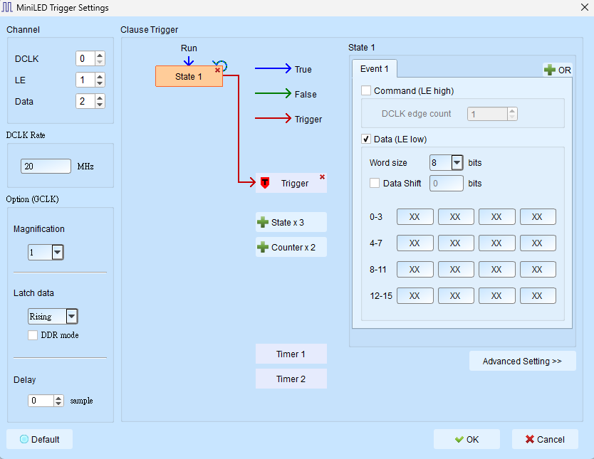
- Channel: Assign DCLK, LE, and Data (channel indices omitted).
- DCLK Rate: DCLK rate (MHz). Default: 20.
- Option (GCLK):
- Magnification: Simulated CLK relative to DCLK (1 / 2 / 4 / 8). Default: 1.
- Latch Data: Rising / Falling. Default: Rising. Disabled (Disable) when DDR mode is checked.
- DDR mode: Dual-edge sampling. Checking enables (Enable) DDR behavior and disables Latch select. Default: cleared.
- Delay: Delay in samples. Default: 0.
- Clause Trigger: See Clause Trigger.
- State: Enter DCLK edge count under Command; enter Data as a data pattern, unused XX.
- Command: Checking enables (Enable) the field. Default: cleared; edge count Default 1.
- Data: Checking enables (Enable) the fields. Default: checked; Size Default index 0 (8-bit width); each field Default XX; Shift Default 0 (cleared).